Visible to Intel only — GUID: lcp1493520992679
Ixiasoft
1. Functional Description—UniPHY
2. Functional Description— Intel® MAX® 10 EMIF IP
3. Functional Description—Hard Memory Interface
4. Functional Description—HPS Memory Controller
5. Functional Description—HPC II Controller
6. Functional Description—QDR II Controller
7. Functional Description—RLDRAM II Controller
8. Functional Description—RLDRAM 3 PHY-Only IP
9. Functional Description—Example Designs
10. Introduction to UniPHY IP
11. Latency for UniPHY IP
12. Timing Diagrams for UniPHY IP
13. External Memory Interface Debug Toolkit
14. Upgrading to UniPHY-based Controllers from ALTMEMPHY-based Controllers
1.1. I/O Pads
1.2. Reset and Clock Generation
1.3. Dedicated Clock Networks
1.4. Address and Command Datapath
1.5. Write Datapath
1.6. Read Datapath
1.7. Sequencer
1.8. Shadow Registers
1.9. UniPHY Interfaces
1.10. UniPHY Signals
1.11. PHY-to-Controller Interfaces
1.12. Using a Custom Controller
1.13. AFI 3.0 Specification
1.14. Register Maps
1.15. Ping Pong PHY
1.16. Efficiency Monitor and Protocol Checker
1.17. UniPHY Calibration Stages
1.18. Document Revision History
1.7.1.1. Nios® II-based Sequencer Function
1.7.1.2. Nios® II-based Sequencer Architecture
1.7.1.3. Nios® II-based Sequencer SCC Manager
1.7.1.4. Nios® II-based Sequencer RW Manager
1.7.1.5. Nios® II-based Sequencer PHY Manager
1.7.1.6. Nios® II-based Sequencer Data Manager
1.7.1.7. Nios® II-based Sequencer Tracking Manager
1.7.1.8. Nios® II-based Sequencer Processor
1.7.1.9. Nios® II-based Sequencer Calibration and Diagnostics
1.17.1. Calibration Overview
1.17.2. Calibration Stages
1.17.3. Memory Initialization
1.17.4. Stage 1: Read Calibration Part One—DQS Enable Calibration and DQ/DQS Centering
1.17.5. Stage 2: Write Calibration Part One
1.17.6. Stage 3: Write Calibration Part Two—DQ/DQS Centering
1.17.7. Stage 4: Read Calibration Part Two—Read Latency Minimization
1.17.8. Calibration Signals
1.17.9. Calibration Time
4.1. Features of the SDRAM Controller Subsystem
4.2. SDRAM Controller Subsystem Block Diagram
4.3. SDRAM Controller Memory Options
4.4. SDRAM Controller Subsystem Interfaces
4.5. Memory Controller Architecture
4.6. Functional Description of the SDRAM Controller Subsystem
4.7. SDRAM Power Management
4.8. DDR PHY
4.9. Clocks
4.10. Resets
4.11. Port Mappings
4.12. Initialization
4.13. SDRAM Controller Subsystem Programming Model
4.14. Debugging HPS SDRAM in the Preloader
4.15. SDRAM Controller Address Map and Register Definitions
4.16. Document Revision History
10.7.1. DDR2, DDR3, and LPDDR2 Resource Utilization in Arria V Devices
10.7.2. DDR2 and DDR3 Resource Utilization in Arria II GZ Devices
10.7.3. DDR2 and DDR3 Resource Utilization in Stratix III Devices
10.7.4. DDR2 and DDR3 Resource Utilization in Stratix IV Devices
10.7.5. DDR2 and DDR3 Resource Utilization in Arria V GZ and Stratix V Devices
10.7.6. QDR II and QDR II+ Resource Utilization in Arria V Devices
10.7.7. QDR II and QDR II+ Resource Utilization in Arria II GX Devices
10.7.8. QDR II and QDR II+ Resource Utilization in Arria II GZ, Arria V GZ, Stratix III, Stratix IV, and Stratix V Devices
10.7.9. RLDRAM II Resource Utilization in Arria® V Devices
10.7.10. RLDRAM II Resource Utilization in Arria® II GZ, Arria® V GZ, Stratix® III, Stratix® IV, and Stratix® V Devices
13.1. User Interface
13.2. Setup and Use
13.3. Operational Considerations
13.4. Troubleshooting
13.5. Debug Report for Arria V and Cyclone V SoC Devices
13.6. On-Chip Debug Port for UniPHY-based EMIF IP
13.7. Example Tcl Script for Running the Legacy EMIF Debug Toolkit
13.8. Document Revision History
Visible to Intel only — GUID: lcp1493520992679
Ixiasoft
16.10.3. Understanding the Custom Traffic Generator User Interface
The Custom Traffic Generator interface lets you configure data patterns, the bytes to be enabled, the addressing mode, and the order in which traffic is organized.
The interface has three tabs:
- Data tab
- Address tab
- Loops tab
Data Tab
The Data tab is divided into Data Pins and Data Mask Pins sections.
Figure 216. Data Tab

The Data Pins section helps with customizing the patterns selected for the data pins. You can choose between two options for Data Mode:
- PRBS The default write data to all the data pins.
- Fixed Pattern Lets you specify a pattern to be written to the memory.
Select the All Pins option when you want to write the same data pattern to all the data pins. If data must be individually assigned to the data pins, you must enter the data value for each individual pin. The width of the data entered is based on the AVL_TO_DQ_WIDTH_RATIO, which is based on the ratio of the memory clock to the user clock.
All data bytes are enabled by default; the Data Mask Pins section lets you disable any of the bytes if you want to. To disable data bytes individually, select Test data mask.
You can choose between two options for Data Mode:
- PRBS Specifies the PRBS pattern to enable or disable data bytes. A 1 denotes a data byte enabled, while a 0 denotes a data byte being masked or disabled.
- Fixed Pattern Lets you enable or disable individual bytes. You can apply byte enables to all pins or to individual bytes. A 1 denotes a data byte enabled, while a 0 denotes a data byte being masked or disabled.
Address Tab
The Address tab lets you configure sequential, random, or random sequential (where the initial start address is random, but sequential thereafter) addressing schemes. The Address tab is divided into Address Mode and Address Configuration sections.
Figure 217. Address Tab

The Address Mode section lets you specify the pattern of addresses generated to access the memory. You can choose between three address modes :
- Sequential Each address is incremented by the Sequential address increment value that you specify. You also specify the Start Address from which the increments begin.
- Random Each address is generated randomly. (You set the number of random addresses on the Loops tab.)
- Random Sequential Each address is generated randomly, and then incremented sequentially. You specify the number of sequential increments in the Number of sequential addresses field.
The Address Configuration section contains the settings with which you configure the address mode that you chose in the Address Mode section. The following settings are available:
- Start address Specifies the starting address for Sequential Address Mode. The maximum address value that can be reached is 1FF_FFFF. (The Traffic Generator 2.0 will accept higher values, but wraps back to 0 after the maximum value has been reached.) The Start address setting applies only to Sequential Address Mode.
- Number of sequential addresses Specifies the number of sequential addresses generated after the first random address generated. This setting applies only in Random sequential mode.
- Sequential address increment Specifies the size of increment between each address in the Sequential address mode and Random sequential address mode.
- Return to start address Specifies that the address value generated return back to the value entered in the Start Address field, after a block of transactions to the memory has completed. This setting applies only to Sequential address mode.
- Address masking Masking provides additional options for exploring certain specific address spaces in memory:
- Disabled does not enable masking, and increments address based on the selected Address Mode.
- Fixed cycling allows you to restrict the addressing to a specific row or a specific bank, which you can specify in the corresponding Mask Value field.
Loops Tab
The Loops tab lets you order the transactions to the memory as desired. A unit size of transactions to the memory is defined as a block; a block includes a set of write transaction(s) immediately followed by a set of read transaction(s).
Figure 218. Loops Tab
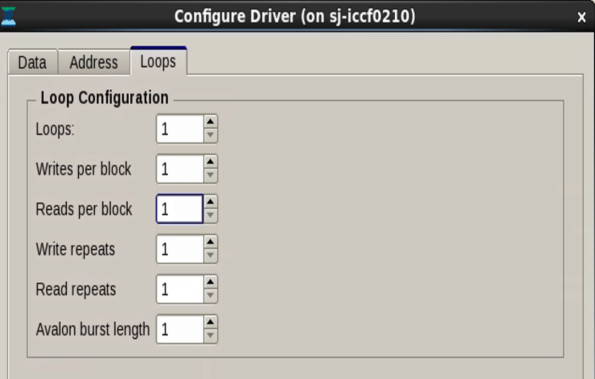
The Loops tab provides the following configuration options:
- Loops Specifies the number of blocks of transactions to be sent to the memory. This option helps to extend the range of addresses that the controller can access. The address range is incremented as each loop is executed, unless you specify Return to Start Address, which causes each loop to begin from the same start address. The range of supported values for the Loops option is from 1 to 4095.
- Writes per block Specifies the size of the block (that is, the number of consecutive write operations that can be issued in a single block). The range of values for this option is as follows:
- When address masking is disabled, the number of writes per block supported is 1 to 4094.
- When address masking is enabled, the maximum number of writes issued inside a block is 255.
- Reads per block Specifies the number of consecutive read operations that can be issued in a single block, immediately following the consecutive writes issued. The number of reads per block should be identical to the number of writes per block, because data mismatches can occur when the two values are not identical. The range of values for this option is as follows:
- When address masking is disabled, the number of reads per block supported is 1 to 4094.
- When address masking is enabled, the maximum number of reads issued inside a block is 255.
- Write repeats Specifies the number of times each write command is issued in repetition to the same address. A maximum number of 255 repeat write transactions can be issued. The repeat writes are issued immediately after the first write command has been issued.
- Read repeats Specifies the number of times each read command is issued in repetition to the same address. A maximum number of 255 repeat read transactions can be issued. The repeat reads are issued immediately after the first read command has been issued.
- Avalon burst length Specifies the length of each Avalon burst. The value of this field should be less than the Sequential address increment specified on the Address tab. The number of write and read repeats default to 1 if the Avalon burst length is greater than 1.