1.6.12. Using the Core Clock Frequency and Current Ramp Up Period Parameters
On chip noise can be split into two categories. High frequency noise and low frequency noise. High frequency noise is generated by the transistor switching activities and is mainly regulated by die capacitance. Low frequency noise is generated by the average current fluctuation and has to be regulated by on package and PCB decoupling capacitors. It takes time for the average current to ramp up or down. Some applications, such as DSP and matrix operation, can cause current surge in a short period while current change in normal applications may take 25 clock cycles or more to settle down. The current transition time affects the PCB decoupling requirement and can be used to de-rate the target impedance. For more details refer to Improving the Target Impedance Method for PCB Decoupling of Core Power.
Some PDN tool variants allow you to add data for the Core Clock Frequency and Current Ramp Up Period parameters using the pull-down menus. These values tell the tool how to calculate the current ramp up period for transient events, sometimes reducing transient current changes. The values relate to how fast the clock for the section is running, and the length of the data pipeline. Given a transient change in the input data, there are clock cycles in the pipeline for the algorithm to deliver the results. If the input data change activates a broad yet short pipeline, the transient is abrupt. This results in a large current change for the number of logic elements you are using. If the pipeline is narrow and long, the overall change in current usage is proportionately smaller
You can set the Core Clock Frequency parameter to a High, Medium, Low, or Custom set of input frequencies. The Custom option allows you to enter a specific input frequency.
The Current Ramp Up Period parameter allows you to specify the number of clock cycles consumed by the pipeline. You can select a High, Medium, Low, or Custom setting. Altera recommends using a smaller value unless you have already entered a complete design in Quartus and determined the precise value.
Using the Core Clock Frequency and Current Ramp Up Period parameters has the effect of de-rating the target impedance at higher frequencies so that it ramps-up and is easier to meet.
In this example, entering a Medium 300MHz Core Clock Frequency and a Low 25 clock cycle Current Ramp Up Period , the number of decoupling capacitors required to meet the VCC supply is reduced from 301 to 37.
The Figures below show the capacitors required and impedance plot for the VCC supply.
Figure 27. VCC Supply Capacitors and PDN Performance When Using the Core Clock Frequency and Current Ramp Up Period Parameters
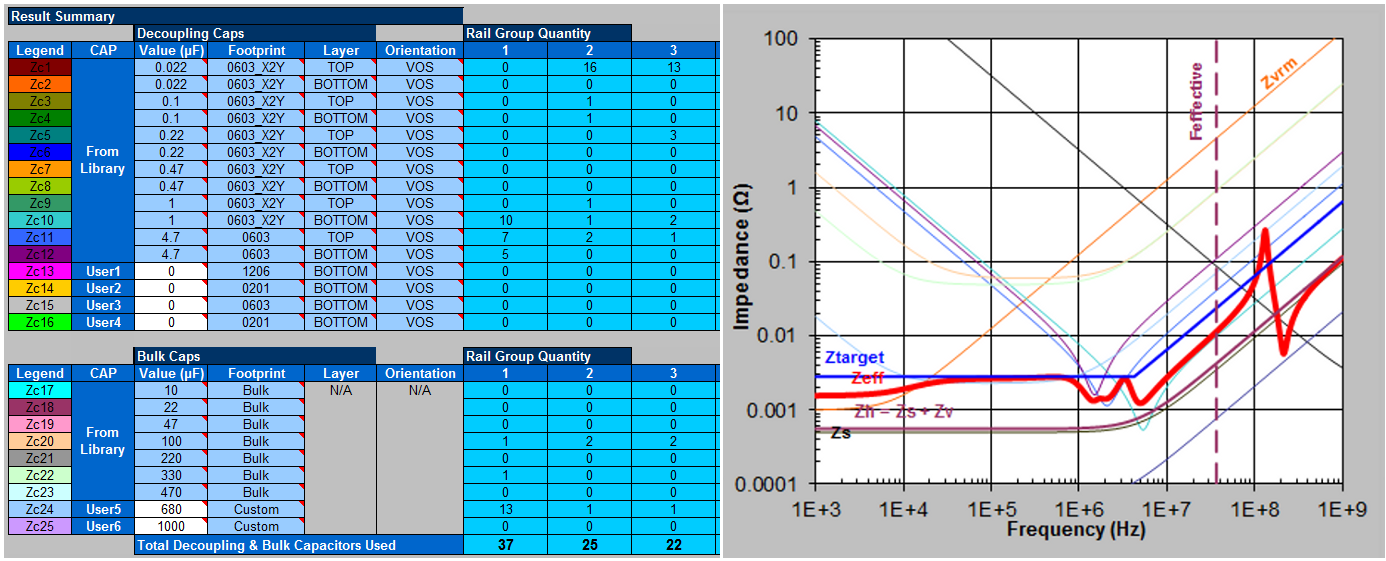
Reducing the number of VCC supply capacitors from 301 to 37 is a big improvement. The Core Clock Frequency and Current Ramp Up Period parameters can be applied earlier in the flow of this application note but it is generally beneficial to optimize the efficiency of the PDN before applying such de-rating effects.
The VCC, VCCT_GXB, and VCCR_GXB supplies are now decoupled with an effective and acceptable decoupling solution for this PCB with the estimated current requirements.