3.7.2. Toolkit GUI Settings
The Serial Lite IV IP toolkit offers an easy-to-manage user interface.
The Serial Lite IV IP toolkit user interface has four tabs.
- The GUI configuration tab lets you set the JTAG master settings to enable communication between the development kit and toolkit.
- The MAC and PHY tab implements various CSR for both the hardened custom PCS core and the MAC soft logic.
- The Traffic Statistics and Bandwidth Performance tab implements various CSR for the Demo Management module to configure the traffic generator and checker. Additionally, the tab also provides a real-time bandwidth calculation measurement result based on the traffic modules instantiated in the example design.
- The Help tab provides useful next-step troubleshooting information based on the assertion and deassertion of specific status registers or output ports if any errors happen after the link initialization is executed.
The MAC and PHY tab shows a step-by-step guide for link initialization and real-time status monitoring of a Serial Lite IV IP link.
The toolkit continuously reads and displays all of the essential status registers related to the Serial Lite IV IP link after you execute the following stages:
- Click Assert system reset and Deassert system reset to perform a full system reset.
- Click Link initialization to perform link initialization with internal/external loopback enabled.
- Click Read status to poll all corresponding status registers and output ports from both hardened custom PCS and MAC soft logic.
- Click Read FEC statistics to generate the FEC statistics report after steps 1–3 complete successfully and the link is up and running.
Figure 21. MAC and PHY Tab
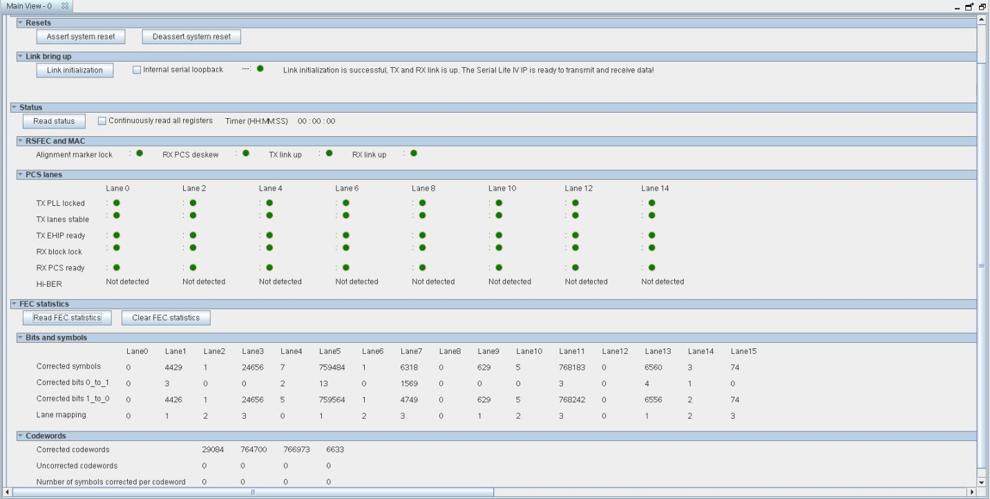
Note: The toolkit user interface changes dynamically to illustrate each execution stage.
In case of any failure, the toolkit diagnoses the failure based on the various status bits. These status bits are based on the register bank or output port from the hardened custom PCS core or MAC soft logic. The corresponding next-step debugging information is displayed in the Help tab.
Figure 22. Traffic Statistics and Bandwidth Performance Tab
You can configure the traffic generator and checker to run in user-specified mode using the Traffic Statistics and Bandwidth Performance tab. You can turn on the Sink RX to Source TX parameter to run the hardware design example in slave mode. When this parameter is enabled, the traffic flows from sink to source. You can also read the traffic statistics in this tab. Additionally, the toolkit also calculates and displays the real-time effective bandwidth based on the design example.
Figure 23. Help Tab
The Help tab provides useful next-step debugging information based on the errors or status registers reported from the MAC and PCS status in the MAC and PHY tab.