Visible to Intel only — GUID: aev1678301530846
Ixiasoft
1. About the R-Tile Avalon® Streaming Intel® FPGA IP for PCI Express
2. IP Architecture and Functional Description
3. Advanced Features
4. Interfaces
5. Parameters
6. Troubleshooting/Debugging
7. R-Tile Avalon® Streaming Intel® FPGA IP for PCI Express* User Guide Archives
8. Document Revision History for the R-Tile Avalon® Streaming Intel® FPGA IP for PCI Express* User Guide
A. Configuration Space Registers
B. Root Port Enumeration
C. Implementation of Address Translation Services (ATS) in Endpoint Mode
D. Packets Forwarded to the User Application in TLP Bypass Mode
E. Margin Masks for the R-Tile Avalon Streaming Intel FPGA IP for PCI Express
3.2.2.5.1. VirtIO Common Configuration Capability Register (Address: 0x012)
3.2.2.5.2. VirtIO Common Configuration BAR Indicator Register (Address: 0x013)
3.2.2.5.3. VirtIO Common Configuration BAR Offset Register (Address: 0x014)
3.2.2.5.4. VirtIO Common Configuration Structure Length Register (Address 0x015)
3.2.2.5.5. VirtIO Notifications Capability Register (Address: 0x016)
3.2.2.5.6. VirtIO Notifications BAR Indicator Register (Address: 0x017)
3.2.2.5.7. VirtIO Notifications BAR Offset Register (Address: 0x018)
3.2.2.5.8. VirtIO Notifications Structure Length Register (Address: 0x019)
3.2.2.5.9. VirtIO Notifications Notify Off Multiplier Register (Address: 0x01A)
3.2.2.5.10. VirtIO ISR Status Capability Register (Address: 0x02F)
3.2.2.5.11. VirtIO ISR Status BAR Indicator Register (Address: 0x030)
3.2.2.5.12. VirtIO ISR Status BAR Offset Register (Address: 0x031)
3.2.2.5.13. VirtIO ISR Status Structure Length Register (Address: 0x032)
3.2.2.5.14. VirtIO Device Specific Capability Register (Address: 0x033)
3.2.2.5.15. VirtIO Device Specific BAR Indicator Register (Address: 0x034)
3.2.2.5.16. VirtIO Device Specific BAR Offset Register (Address 0x035)
3.2.2.5.17. VirtIO Device Specific Structure Length Register (Address: 0x036)
3.2.2.5.18. VirtIO PCI Configuration Access Capability Register (Address: 0x037)
3.2.2.5.19. VirtIO PCI Configuration Access BAR Indicator Register (Address: 0x038)
3.2.2.5.20. VirtIO PCI Configuration Access BAR Offset Register (Address: 0x039)
3.2.2.5.21. VirtIO PCI Configuration Access Structure Length Register (Address: 0x03A)
3.2.2.5.22. VirtIO PCI Configuration Access Data Register (Address: 0x03B)
4.3.1. Avalon® Streaming Interface
4.3.2. Precision Time Measurement (PTM) Interface (Endpoint Only)
4.3.3. Interrupt Interface
4.3.4. Hard IP Reconfiguration Interface
4.3.5. Error Interface
4.3.6. Completion Timeout Interface
4.3.7. Configuration Intercept Interface
4.3.8. Power Management Interface
4.3.9. Hard IP Status Interface
4.3.10. Page Request Services (PRS) Interface (Endpoint Only)
4.3.11. Function-Level Reset (FLR) Interface (Endpoint Only)
4.3.12. SR-IOV VF Error Flag Interface (Endpoint Only)
4.3.13. General Purpose VSEC Interface
5.2.3.1. Device Capabilities
5.2.3.2. VirtIO Parameters
5.2.3.3. Link Capabilities
5.2.3.4. Legacy Interrupt Pin Register
5.2.3.5. MSI Capabilities
5.2.3.6. MSI-X Capabilities
5.2.3.7. Slot Capabilities
5.2.3.8. Latency Tolerance Reporting (LTR)
5.2.3.9. Process Address Space ID (PASID)
5.2.3.10. Device Serial Number Capability
5.2.3.11. Page Request Service (PRS)
5.2.3.12. Access Control Service (ACS)
5.2.3.13. Power Management
5.2.3.14. Vendor Specific Extended Capability (VSEC) Registers
5.2.3.15. TLP Processing Hints (TPH)
5.2.3.16. Address Translation Services (ATS) Capabilities
5.2.3.17. Precision Time Measurement (PTM)
Visible to Intel only — GUID: aev1678301530846
Ixiasoft
6.6.4.5.4. Lane Margining
The R-Tile Debug Toolkit supports electrical lane margining that allows you to assess the electrical health for each channel. This feature allows you to:
- Assess the voltage margin (vertical) from sampling point to top and bottom.
- Assess the time margin (horizontal) from sampling point to left and right. However, please note that the R-Tile Debug Toolkit will only report the minor margin measured between the left margin and the right margin.
- Perform lane margining with the following configurations:
- Configuration Mode 0 (1x16) and Configuration Mode 1 (2x8)
- 8.0 GT/s (PCIe 3.0) at BER 10e-9
- 16.0 GT/s (PCIe 3.0) at BER 10e-9
- 32.0 GT/s (PCIe 3.0) at BER 10e-9
- Perform automatic comparison of lane margining results versus the reference mask at BER 10e-9 and BER 10e-12. The lane margining exercise is performed at a BER of 10e-9. However, the tool automatically compares the results against the recommended mask for both BER 10e-9 and BER 10e-12.
Note: Intel recommends that the margin for each lane on your board be more than the mask in the horizontal and vertical directions to make sure that the channel is good and meets the PCIe specification. For more information on the Margin Masks, refer to Margin Masks for the R-Tile Avalon Streaming Intel FPGA IP for PCI Express.
Note: The R-Tile Avalon Streaming Intel FPGA IP for PCI Express Lane Margining feature of the Debug Toolkit does not support an independent error sampler for performing the lane margining. The lane margining is performed on the actual data path. As a result, the lane margining may produce uncorrectable errors in the data stream and cause the Link Training and Status State Machine (LTSSM) to go into the Recovery state. You may mask out all errors through the Advanced Error Reporting (AER) registers while performing lane margining, and reset all error counters, error registers, etc. after margining completes.
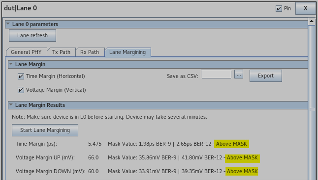
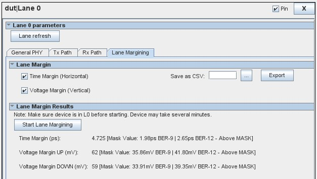
Figure 74. Lane Margining
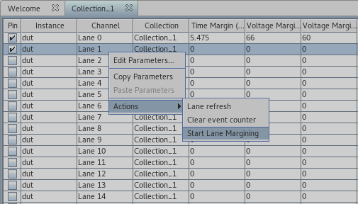
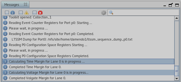
Execute the following procedure to perform lane margining for a given lane:
- Select the targeted lane on the Collection tab.
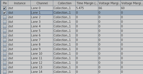
- A new panel is displayed on the Channel Parameters tab. Select the Lane Margining sub-tab.
- Under the Lane Margin section, select Time Margin (Horizontal) and/or Voltage Margin (Vertical).
- Under the Lane Margining Results section, click the Start button. Alternatively, you can right-click on the targeted lane and select Start Lane Margining.
- The lane margining may take several minutes to complete. Wait until the results are displayed.
- Once the lane margining results are available, the Debug Toolkit automatically compares them against the recommended Masks and provides a comparison result by printing Above Mask or Below Mask. This label appears next to the mask values. Refer to Margin Masks for the R-Tile Avalon Streaming Intel FPGA IP for PCI Express for details on the suggested methodology to evaluate your overall link margins.
Note: The Debug Toolkit reports Above Mask if the obtained margin is above the BER 10e-9 mask but less than the BER 10e-12 mask.