Visible to Intel only — GUID: aof1520633281406
Ixiasoft
1. Introduction
2. Quick Start Guide
3. Block and Interface Descriptions
4. Parameters
5. Designing with the IP Core
6. Registers
7. Design Example and Testbench
8. Document Revision History for Intel® L- and H-tile Avalon® Memory-mapped+ IP for PCI Express* User Guide
A. Avalon-MM IP Variants Comparison
B. Root Port BFM
C. BFM Procedures and Functions
D. Troubleshooting and Observing the Link Status
E. Root Port Enumeration
2.1. Design Components
2.2. Directory Structure
2.3. Generating the Design Example
2.4. Simulating the Design Example
2.5. Compiling the Design Example and Programming the Device
2.6. Installing the Linux Kernel Driver
2.7. Running the Design Example Application
2.8. Ensuring the Design Example Meets Timing Requirements
6.1.1. Register Access Definitions
6.1.2. PCI Configuration Header Registers
6.1.3. PCI Express Capability Structures
6.1.4. Intel Defined VSEC Capability Header
6.1.5. Uncorrectable Internal Error Status Register
6.1.6. Uncorrectable Internal Error Mask Register
6.1.7. Correctable Internal Error Status Register
6.1.8. Correctable Internal Error Mask Register
C.1. ebfm_barwr Procedure
C.2. ebfm_barwr_imm Procedure
C.3. ebfm_barrd_wait Procedure
C.4. ebfm_barrd_nowt Procedure
C.5. ebfm_cfgwr_imm_wait Procedure
C.6. ebfm_cfgwr_imm_nowt Procedure
C.7. ebfm_cfgrd_wait Procedure
C.8. ebfm_cfgrd_nowt Procedure
C.9. BFM Configuration Procedures
C.10. BFM Shared Memory Access Procedures
C.11. BFM Log and Message Procedures
C.12. Verilog HDL Formatting Functions
Visible to Intel only — GUID: aof1520633281406
Ixiasoft
2.3. Generating the Design Example
Figure 6. Procedure
- In the Quartus® Prime Pro Edition software, create a new project (File > New Project Wizard).
- Specify the Directory, Name, and Top-Level Entity.
- For Project Type, accept the default value, Empty project. Click Next.
- For Add Files click Next.
- For Family, Device & Board Settings under Family, select Stratix® 10 (GX/SX/MX/TX) and the Target Device for your design. Note that the selected device is only used if you select None in Step 10e below.
- Click Finish.
- In the IP Catalog locate and add the Intel L-/H-Tile Avalon-MM+ for PCI Express IP.
- In the New IP Variant dialog box, specify a name for your IP. Click Create.
- On the IP Settings tabs, specify the parameters for your IP variation.
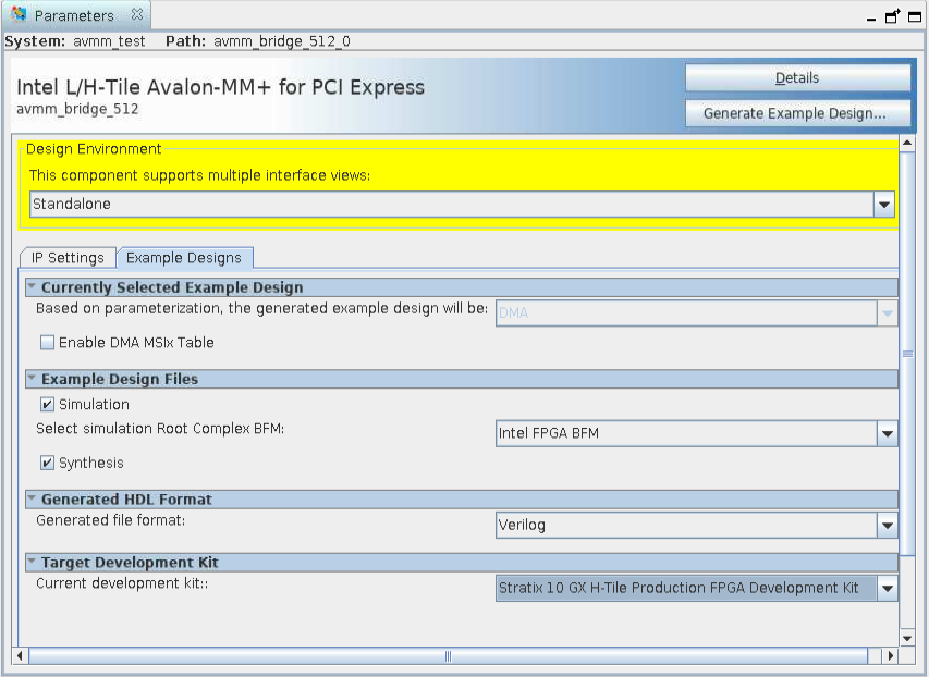
- On the Example Designs tab, make the following selections:
- For Available Example Designs, select DMA.
- For Example Design Files, turn on the Simulation and Synthesis options. If you do not need these simulation or synthesis files, leaving the corresponding option(s) turned off significantly reduces the example design generation time.
- For Select simulation Root Complex BFM, choose the appropriate BFM:
- Intel FPGA BFM: This bus functional model (BFM) supports x16 configurations by downtraining to x8.
- Third-party BFM: If you want to simulate all 16 lanes, use a third-party BFM. Refer to AN-811: Using the Avery BFM for PCI Express Gen3x16 Simulation on Stratix® 10 Devices for information about simulating with the Avery BFM.
- For Generated HDL Format, only Verilog is available in the current release.
- For Target Development Kit, select the appropriate option.
Note: If you select None, the generated design example targets the device specified. Otherwise, the design example uses the device on the selected development board. If you intend to test the design in hardware, make the appropriate pin assignments in the .qsf file.
- Select Generate Example Design to create a design example that you can simulate and download to hardware. If you select one of the Stratix® 10 development boards, the device on that board supersedes the device previously selected in the Quartus® Prime Pro Edition project if the devices are different. When the prompt asks you to specify the directory for your example design, you can choose to accept the default directory, <example_design>/avmm_bridge_512_0_example_design
Figure 7. Example Design Tab
 When you generate an Stratix® 10 example design, a file called recommended_pinassignments_s10.txt is created in the directory avmm_bridge_512_0_example_design. 1
 - Click Finish to close the dummy .ip file, which does not have the complete configuration.
- Click No upon receiving the prompt, Recent changes have not been generated. Generate now? since you do not need to generate any file for the design associated with the dummy .ip file.
- Change directory to the example design directory. Open pcie_example_design.qpf in Quartus® Prime Pro Edition.
- Start compilation. This generates the .sof file for the complete example design, which you can download to a board to perform hardware verification.
- Close your project.
1 This file contains the recommended pin assignments for all the pins in the example design. If you chose a GX, SX or MX development kit option in the pull-down menu for Target Development Kit, the pin assignments in the recommended_pinassignments_s10.txt file match those that are in the .qsf file in the same directory. If you chose NONE in the pull-down menu, the .qsf file does not contain any pin assignment. In this case, you can copy the pin assignments in the recommended_pinassignments_s10.txt file to the .qsf file. You can always change any pin assignment in the .qsf file to satisfy your design or board requirements.