Visible to Intel only — GUID: joc1463333802645
Ixiasoft
Intel® Stratix® 10 Devices and Transceiver Channels
PCB Stackup Selection Guideline
Recommendations for High Speed Signal PCB Routing
FPGA Fan-out Region Design
CFP2/CFP4 Connector Board Layout Design Guideline
QSFP+/zSFP/QSFP28 Connector Board Layout Design Guideline
SMA 2.4-mm Layout Design Guideline
Tyco/Amphenol Interlaken Connector Design Guideline
Electrical Specifications
Document Revision History for AN 766: Intel® Stratix® 10 Devices, High Speed Signal Interface Layout Design Guideline
Option 1: Via-In-Pad Topology
Option 2: Dog-bone with GND Cutout at BGA Pad Topology
Option 3: Micro-via Topology
GND Cutout Under BGA Pads in Fan-out Configuration
Comparison of Dog-bone with GND Cutout Under the BGA and Via-in-Pad Configurations
Trace Shape Routing at the BGA Void Area (Tear Drop Configuration)
Visible to Intel only — GUID: joc1463333802645
Ixiasoft
AC Coupling Capacitor Layout and Optimization Guidelines
It is possible to use both the 0402 and 0201 capacitor sizes on boards as AC coupling capacitors on transceiver links.
Figure 38. AC Capacitor Placement and GND Cutout on PCB with Stripline Routing on Both Ends Structural detail where trace routing is stripline and the AC capacitor is mounted on the top or bottom layers.
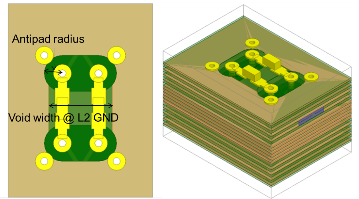
The structural detail includes the following specifications:
- 10 mil drill hole and 20 mil pad
- The cap is mounted on the top layer and the trace breakout is routed on layer 7
- 10 mil stub length
- 0201 capacitor size copper block
- 24 mil x 12 mil x 12 mil
- 0402 capacitor size copper block
- 40 mil x 20 mil x 14 mil
The board stack-up configuration includes the following specifications:
- 24 layers and a thickness of 117 mil
- 8 signal layers, 4 PWR lanes
- Megtron6 material