Visible to Intel only — GUID: mwh1409958798326
Ixiasoft
1. Creating a System with Platform Designer
2. Optimizing Platform Designer System Performance
3. Platform Designer Interconnect
4. Platform Designer System Design Components
5. Creating Platform Designer Components
6. Platform Designer Command-Line Utilities
7. Component Interface Tcl Reference
A. Intel® Quartus® Prime Standard Edition User Guides
1.1. Platform Designer Interface Support
1.2. Platform Designer System Design Flow
1.3. Starting or Opening a Project in Platform Designer
1.4. Viewing a Platform Designer System
1.5. Adding IP Components to a System
1.6. Connecting System Components
1.7. Specifying Interconnect Requirements
1.8. Defining Instance Parameters
1.9. Implementing Performance Monitoring
1.10. Configuring Platform Designer System Security
1.11. Upgrading Outdated IP Components
1.12. Synchronizing System Component Information
1.13. Generating a Platform Designer System
1.14. Simulating a Platform Designer System
1.15. Integrating a Platform Designer System with the Intel® Quartus® Prime Software
1.16. Managing Hierarchical Platform Designer Systems
1.17. Creating a System with Platform Designer Revision History
1.13.1. Generation Dialog Box Options
1.13.2. Specifying the Generation ID
1.13.3. Files Generated for IP Cores and Platform Designer Systems
1.13.4. Generating System Testbench Files
1.13.5. Generating Example Designs for IP Components
1.13.6. Generating the HPS IP Component System View Description File
1.13.7. Generating Header Files for Master Components
1.16.1. Adding a Subsystem to a Platform Designer System
1.16.2. Viewing and Traversing Subsystem Contents
1.16.3. Editing a Subsystem
1.16.4. Changing a Component's Hierarchy Level
1.16.5. Saving a Subsystem
1.16.6. Exporting a System as an IP Component
1.16.7. Hierarchical System Using Instance Parameters Example
2.1. Designing with Avalon® and AXI Interfaces
2.2. Using Hierarchy in Systems
2.3. Using Concurrency in Memory-Mapped Systems
2.4. Inserting Pipeline Stages to Increase System Frequency
2.5. Using Bridges
2.6. Increasing Transfer Throughput
2.7. Reducing Logic Utilization
2.8. Reducing Power Consumption
2.9. Reset Polarity and Synchronization in Platform Designer
2.10. Optimizing Platform Designer System Performance Design Examples
2.11. Optimizing Platform Designer System Performance Revision History
3.1. Memory-Mapped Interfaces
3.2. Avalon® Streaming Interfaces
3.3. Interrupt Interfaces
3.4. Clock Interfaces
3.5. Reset Interfaces
3.6. Conduits
3.7. Interconnect Pipelining
3.8. Error Correction Coding (ECC) in Platform Designer Interconnect
3.9. AMBA* 3 AXI Protocol Specification Support (version 1.0)
3.10. AMBA* 3 APB Protocol Specification Support (version 1.0)
3.11. AMBA* 4 AXI Memory-Mapped Interface Support (version 2.0)
3.12. AMBA* 4 AXI Streaming Interface Support (version 1.0)
3.13. AMBA* 4 AXI-Lite Protocol Specification Support (version 2.0)
3.14. Port Roles (Interface Signal Types)
3.15. Platform Designer Interconnect Revision History
3.1.1. Platform Designer Packet Format
3.1.2. Interconnect Domains
3.1.3. Master Network Interfaces
3.1.4. Slave Network Interfaces
3.1.5. Arbitration
3.1.6. Memory-Mapped Arbiter
3.1.7. Datapath Multiplexing Logic
3.1.8. Width Adaptation
3.1.9. Burst Adapter
3.1.10. Waitrequest Allowance Adapter
3.1.11. Read and Write Responses
3.1.12. Platform Designer Address Decoding
3.5.4.3.1. Reset Sequencer Status Register
3.5.4.3.2. Reset Sequencer Interrupt Enable Register
3.5.4.3.3. Reset Sequencer Control Register
3.5.4.3.4. Reset Sequencer Software Sequenced Reset Assert Control Register
3.5.4.3.5. Reset Sequencer Software Sequenced Reset Deassert Control Register
3.5.4.3.6. Reset Sequencer Software Direct Controlled Resets
3.5.4.3.7. Reset Sequencer Software Reset Masking
3.11.1. Burst Support
3.11.2. QoS
3.11.3. Regions
3.11.4. Write Response Dependency
3.11.5. AWCACHE and ARCACHE
3.11.6. Width Adaptation and Data Packing in Platform Designer
3.11.7. Ordering Model
3.11.8. Read and Write Allocate
3.11.9. Locked Transactions
3.11.10. Memory Types
3.11.11. Mismatched Attributes
3.11.12. Signals
3.14.1. AXI Master Interface Signal Types
3.14.2. AXI Slave Interface Signal Types
3.14.3. AMBA* 4 AXI Master Interface Signal Types
3.14.4. AMBA* 4 AXI Slave Interface Signal Types
3.14.5. AMBA* 4 AXI-Stream Master and Slave Interface Signal Types
3.14.6. ACE-Lite Interface Signal Roles
3.14.7. APB Interface Signal Types
3.14.8. Avalon® Memory-Mapped Interface Signal Roles
3.14.9. Avalon® Streaming Interface Signal Roles
3.14.10. Avalon® Clock Source Signal Roles
3.14.11. Avalon® Clock Sink Signal Roles
3.14.12. Avalon® Conduit Signal Roles
3.14.13. Avalon® Tristate Conduit Signal Roles
3.14.14. Avalon® Tri-State Slave Interface Signal Types
3.14.15. Avalon® Interrupt Sender Signal Roles
3.14.16. Avalon® Interrupt Receiver Signal Roles
4.1. Bridges
4.2. Error Response Slave
4.3. Tri-State Components
4.4. Test Pattern Generator and Checker Cores
4.5. Avalon® -ST Splitter Core
4.6. Avalon® -ST Delay Core
4.7. Avalon® -ST Round Robin Scheduler
4.8. Avalon® Packets to Transactions Converter
4.9. Avalon® -ST Streaming Pipeline Stage
4.10. Streaming Channel Multiplexer and Demultiplexer Cores
4.11. Single-Clock and Dual-Clock FIFO Cores
4.12. Platform Designer System Design Components Revision History
4.4.4.1. data_source_reset()
4.4.4.2. data_source_init()
4.4.4.3. data_source_get_id()
4.4.4.4. data_source_get_supports_packets()
4.4.4.5. data_source_get_num_channels()
4.4.4.6. data_source_get_symbols_per_cycle()
4.4.4.7. data_source_get_enable()
4.4.4.8. data_source_set_enable()
4.4.4.9. data_source_get_throttle()
4.4.4.10. data_source_set_throttle()
4.4.4.11. data_source_is_busy()
4.4.4.12. data_source_fill_level()
4.4.4.13. data_source_send_data()
4.4.5.1. data_sink_reset()
4.4.5.2. data_sink_init()
4.4.5.3. data_sink_get_id()
4.4.5.4. data_sink_get_supports_packets()
4.4.5.5. data_sink_get_num_channels()
4.4.5.6. data_sink_get_symbols_per_cycle()
4.4.5.7. data_sink_get_enable()
4.4.5.8. data_sink_set enable()
4.4.5.9. data_sink_get_throttle()
4.4.5.10. data_sink_set_throttle()
4.4.5.11. data_sink_get_packet_count()
4.4.5.12. data_sink_get_error_count()
4.4.5.13. data_sink_get_symbol_count()
4.4.5.14. data_sink_get_exception()
4.4.5.15. data_sink_exception_is_exception()
4.4.5.16. data_sink_exception_has_data_error()
4.4.5.17. data_sink_exception_has_missing_sop()
4.4.5.18. data_sink_exception_has_missing_eop()
4.4.5.19. data_sink_exception_signalled_error()
4.4.5.20. data_sink_exception_channel()
5.1. Platform Designer Components
5.2. Design Phases of an IP Component
5.3. Create IP Components in the Platform Designer Component Editor
5.4. Specify IP Component Type Information
5.5. Create an HDL File in the Platform Designer Component Editor
5.6. Create an HDL File Using a Template in the Platform Designer Component Editor
5.7. Specify Synthesis and Simulation Files in the Platform Designer Component Editor
5.8. Add Signals and Interfaces in the Platform Designer Component Editor
5.9. Specify Parameters in the Platform Designer Component Editor
5.10. Declaring SystemVerilog Interfaces in _hw.tcl
5.11. User Alterable HDL Parameters in _hw.tcl
5.12. Scripting Wire-Level Expressions
5.13. Control Interfaces Dynamically with an Elaboration Callback
5.14. Control File Generation Dynamically with Parameters and a Fileset Callback
5.15. Create a Composed Component or Subsystem
5.16. Create an IP Component with Platform Designer a System View Different from the Generated Synthesis Output Files
5.17. Add Component Instances to a Static or Generated Component
5.18. Creating Platform Designer Components Revision History
5.7.1. Specify HDL Files for Synthesis in the Platform Designer Component Editor
5.7.2. Analyze Synthesis Files in the Platform Designer Component Editor
5.7.3. Name HDL Signals for Automatic Interface and Type Recognition in the Platform Designer Component Editor
5.7.4. Specify Files for Simulation in the Component Editor
5.7.5. Include an Internal Register Map Description in the .svd for Slave Interfaces Connected to an HPS Component
6.1. Run the Platform Designer Editor with qsys-edit
6.2. Scripting IP Core Generation
6.3. Display Available IP Components with ip-catalog
6.4. Create an .ipx File with ip-make-ipx
6.5. Generate Simulation Scripts
6.6. Generate a Platform Designer System with qsys-script
6.7. Platform Designer Scripting Command Reference
6.8. Platform Designer Scripting Property Reference
6.9. Platform Designer Command-Line Interface Revision History
6.7.1.1. create_system
6.7.1.2. export_hw_tcl
6.7.1.3. get_device_families
6.7.1.4. get_devices
6.7.1.5. get_module_properties
6.7.1.6. get_module_property
6.7.1.7. get_project_properties
6.7.1.8. get_project_property
6.7.1.9. load_system
6.7.1.10. save_system
6.7.1.11. set_module_property
6.7.1.12. set_project_property
6.7.2.1. get_composed_connections
6.7.2.2. get_composed_connection_parameter_value
6.7.2.3. get_composed_connection_parameters
6.7.2.4. get_composed_instance_assignment
6.7.2.5. get_composed_instance_assignments
6.7.2.6. get_composed_instance_parameter_value
6.7.2.7. get_composed_instance_parameters
6.7.2.8. get_composed_instances
6.7.3.1. add_instance
6.7.3.2. apply_instance_preset
6.7.3.3. create_ip
6.7.3.4. add_component
6.7.3.5. duplicate_instance
6.7.3.6. enable_instance_parameter_update_callback
6.7.3.7. get_instance_assignment
6.7.3.8. get_instance_assignments
6.7.3.9. get_instance_documentation_links
6.7.3.10. get_instance_interface_assignment
6.7.3.11. get_instance_interface_assignments
6.7.3.12. get_instance_interface_parameter_property
6.7.3.13. get_instance_interface_parameter_value
6.7.3.14. get_instance_interface_parameters
6.7.3.15. get_instance_interface_port_property
6.7.3.16. get_instance_interface_ports
6.7.3.17. get_instance_interface_properties
6.7.3.18. get_instance_interface_property
6.7.3.19. get_instance_interfaces
6.7.3.20. get_instance_parameter_property
6.7.3.21. get_instance_parameter_value
6.7.3.22. get_instance_parameter_values
6.7.3.23. get_instance_parameters
6.7.3.24. get_instance_port_property
6.7.3.25. get_instance_properties
6.7.3.26. get_instance_property
6.7.3.27. get_instances
6.7.3.28. is_instance_parameter_update_callback_enabled
6.7.3.29. remove_instance
6.7.3.30. set_instance_parameter_value
6.7.3.31. set_instance_parameter_values
6.7.3.32. set_instance_property
6.7.4.1. add_connection
6.7.4.2. auto_connect
6.7.4.3. get_connection_parameter_property
6.7.4.4. get_connection_parameter_value
6.7.4.5. get_connection_parameters
6.7.4.6. get_connection_properties
6.7.4.7. get_connection_property
6.7.4.8. get_connections
6.7.4.9. remove_connection
6.7.4.10. remove_dangling_connections
6.7.4.11. set_connection_parameter_value
6.7.5.1. add_interface
6.7.5.2. get_exported_interface_sysinfo_parameter_value
6.7.5.3. get_exported_interface_sysinfo_parameters
6.7.5.4. get_interface_port_property
6.7.5.5. get_interface_ports
6.7.5.6. get_interface_properties
6.7.5.7. get_interface_property
6.7.5.8. get_interfaces
6.7.5.9. get_port_properties
6.7.5.10. remove_interface
6.7.5.11. set_interface_port_property
6.7.5.12. set_interface_property
6.7.7.1. auto_assign_base_addresses
6.7.7.2. auto_assign_irqs
6.7.7.3. auto_assign_system_base_addresses
6.7.7.4. get_interconnect_requirement
6.7.7.5. get_interconnect_requirements
6.7.7.6. get_parameter_properties
6.7.7.7. lock_avalon_base_address
6.7.7.8. send_message
6.7.7.9. set_interconnect_requirement
6.7.7.10. set_use_testbench_naming_pattern
6.7.7.11. unlock_avalon_base_address
6.7.7.12. get_testbench_dutname
6.7.7.13. get_use_testbench_naming_pattern
6.8.1. Connection Properties
6.8.2. Design Environment Type Properties
6.8.3. Direction Properties
6.8.4. Element Properties
6.8.5. Instance Properties
6.8.6. Interface Properties
6.8.7. Message Levels Properties
6.8.8. Module Properties
6.8.9. Parameter Properties
6.8.10. Parameter Status Properties
6.8.11. Parameter Type Properties
6.8.12. Port Properties
6.8.13. Project Properties
6.8.14. System Info Type Properties
6.8.15. Units Properties
6.8.16. Validation Properties
6.8.17. Interface Direction
6.8.18. File Set Kind
6.8.19. Access Type
6.8.20. Instantiation HDL File Properties
6.8.21. Instantiation Interface Duplicate Type
6.8.22. Instantiation Interface Properties
6.8.23. Instantiation Properties
6.8.24. Port Properties
6.8.25. VHDL Type
7.1.1.1. add_interface
7.1.1.2. add_interface_port
7.1.1.3. get_interfaces
7.1.1.4. get_interface_assignment
7.1.1.5. get_interface_assignments
7.1.1.6. get_interface_ports
7.1.1.7. get_interface_properties
7.1.1.8. get_interface_property
7.1.1.9. get_port_properties
7.1.1.10. get_port_property
7.1.1.11. set_interface_assignment
7.1.1.12. set_interface_property
7.1.1.13. set_port_property
7.1.1.14. set_interface_upgrade_map
7.1.4.1. add_documentation_link
7.1.4.2. get_module_assignment
7.1.4.3. get_module_assignments
7.1.4.4. get_module_ports
7.1.4.5. get_module_properties
7.1.4.6. get_module_property
7.1.4.7. send_message
7.1.4.8. set_module_assignment
7.1.4.9. set_module_property
7.1.4.10. add_hdl_instance
7.1.4.11. package
7.1.5.1. add_instance
7.1.5.2. add_connection
7.1.5.3. get_connections
7.1.5.4. get_connection_parameters
7.1.5.5. get_connection_parameter_value
7.1.5.6. get_instances
7.1.5.7. get_instance_interfaces
7.1.5.8. get_instance_interface_ports
7.1.5.9. get_instance_interface_properties
7.1.5.10. get_instance_property
7.1.5.11. set_instance_property
7.1.5.12. get_instance_properties
7.1.5.13. get_instance_interface_property
7.1.5.14. get_instance_parameters
7.1.5.15. get_instance_parameter_property
7.1.5.16. get_instance_parameter_value
7.1.5.17. get_instance_port_property
7.1.5.18. set_connection_parameter_value
7.1.5.19. set_instance_parameter_value
7.1.6.1. add_fileset
7.1.6.2. add_fileset_file
7.1.6.3. set_fileset_property
7.1.6.4. get_fileset_file_attribute
7.1.6.5. set_fileset_file_attribute
7.1.6.6. get_fileset_properties
7.1.6.7. get_fileset_property
7.1.6.8. get_fileset_sim_properties
7.1.6.9. set_fileset_sim_properties
7.1.6.10. create_temp_file
7.2.1. Script Language Properties
7.2.2. Interface Properties
7.2.3. SystemVerilog Interface Properties
7.2.4. Instance Properties
7.2.5. Parameter Properties
7.2.6. Parameter Type Properties
7.2.7. Parameter Status Properties
7.2.8. Port Properties
7.2.9. Direction Properties
7.2.10. Display Item Properties
7.2.11. Display Item Kind Properties
7.2.12. Display Hint Properties
7.2.13. Module Properties
7.2.14. Fileset Properties
7.2.15. Fileset Kind Properties
7.2.16. Callback Properties
7.2.17. File Attribute Properties
7.2.18. File Kind Properties
7.2.19. File Source Properties
7.2.20. Simulator Properties
7.2.21. Port VHDL Type Properties
7.2.22. System Info Type Properties
7.2.23. Design Environment Type Properties
7.2.24. Units Properties
7.2.25. Operating System Properties
7.2.26. Quartus.ini Type Properties
Visible to Intel only — GUID: mwh1409958798326
Ixiasoft
5.9. Specify Parameters in the Platform Designer Component Editor
Components can include parameterized HDL, which allow users of the component flexibility in meeting their system requirements. For example, a component with a configurable memory size or data width, allows using one HDL implementation in different systems, each with unique parameters values.
The Parameters tab allows you specify the parameters that are used to configure instances of the component in a Platform Designer system. You can specify various properties for each parameter that describe how to display and use the parameter. You can also specify a range of allowed values that are checked during the validation phase. The Parameters table displays the HDL parameters that are declared in the top-level HDL module. If you have not yet created the top-level HDL file, the top-level synthesis file template created from the Files tab include the parameters that you create on the Parameters tab.
When the component includes HDL files, the parameters match those defined in the top-level module, and you cannot add or remove them on the Parameters tab. To add or remove the parameters, edit your HDL source, and then re-analyze the file.
If you create a top-level template HDL file for synthesis with the Component Editor, you can remove the newly-created file from the Synthesis Files list on the Files tab, make your parameter changes, and then re-analyze the top-level synthesis file.
You can use the Parameters table to specify the following information about each parameter:
- Name—Specifies the name of the parameter.
- Default Value—Sets the default value for new instances of the component.
- Editable—Specifies whether or not the user can edit the parameter value.
- Type—Defines the parameter type as string, integer, boolean, std_logic, logic vector, natural, or positive.
- Group—Allows you to group parameters in parameter editor.
- Tooltip—Allows you to add a description of the parameter that appears when the user of the component points to the parameter in the editor.
Figure 152. Parameters Tab in the Platform Designer Components Editor
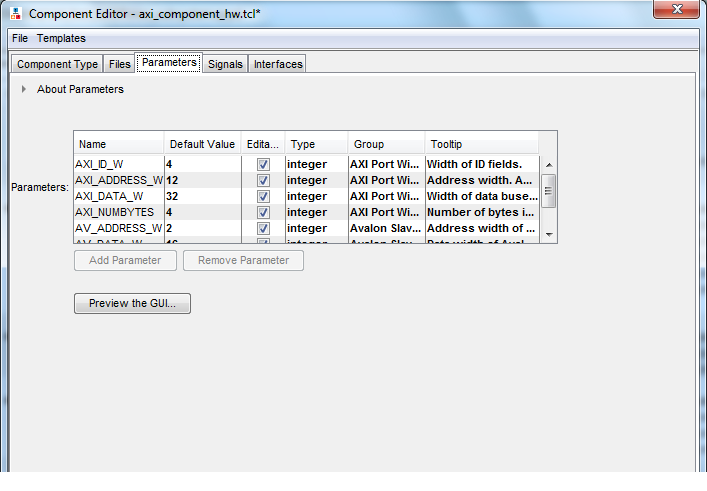
On the Parameters tab, you can click Preview the GUI at any time to see how the declared parameters appear in the parameter editor. Parameters with their default values appear with checks in the Editable column. Editable parameters cannot contain computed expressions. You can group parameters under a common heading or section in the editor with the Group column, and a tooltip helps users of the component understand the function of the parameter. Various parameter properties allow you to customize the component’s parameter editor, such as using radio buttons for parameter selections, or displaying an image.
_hw.tcl Created from Entries in the Parameters Tab
In this example, the first add_parameter command includes commonly-specified properties. The set_parameter_property command specifies each property individually. The Tooltip column on the Parameters tab maps to the DESCRIPTION property, and there is an additional unused UNITS property created in the code. The HDL_PARAMETER property specifies that the value of the parameter is specified in the HDL instance wrapper when creating instances of the component. The Group column in the Parameters tab maps to the display items section with the add_display_item commands.
Note: If a parameter <n> defines the width of a signal, the signal width must follow the format <n-1> : 0.
#
# parameters
#
add_parameter AXI_ID_W INTEGER 4 "Width of ID fields"
set_parameter_property AXI_ID_W DEFAULT_VALUE 4
set_parameter_property AXI_ID_W DISPLAY_NAME AXI_ID_W
set_parameter_property AXI_ID_W TYPE INTEGER
set_parameter_property AXI_ID_W UNITS None
set_parameter_property AXI_ID_W DESCRIPTION "Width of ID fields"
set_parameter_property AXI_ID_W HDL_PARAMETER true
add_parameter AXI_ADDRESS_W INTEGER 12
set_parameter_property AXI_ADDRESS_W DEFAULT_VALUE 12

add_parameter AXI_DATA_W INTEGER 32
...
#
# display items
#
add_display_item "AXI Port Widths" AXI_ID_W PARAMETER ""
Note:
If an AXI slave's ID bit width is smaller than required for your system, the AXI slave response may not reach all AXI masters. The formula of an AXI slave ID bit width is calculated as follows:
maximum_master_id_width_in_the_interconnect + log2 (number_of_masters_in_the_same_interconnect)
For example, if an AXI slave connects to three AXI masters and the maximum AXI master ID length of the three masters is 5 bits, then the AXI slave ID is 7 bits, and is calculated as follows:
5 bits + 2 bits (log2(3 masters)) = 7
| AXI Master Parameters | AXI Slave Parameters |
|---|---|
| readIssuingCapability | readAcceptanceCapability |
| writeIssuingCapability | writeAcceptanceCapability |
| combinedIssuingCapability | combinedAcceptanceCapability |
| readDataReorderingDepth |