Visible to Intel only — GUID: hrr1567781035595
Ixiasoft
Visible to Intel only — GUID: hrr1567781035595
Ixiasoft
A.2.1. Power Guidelines
This section describes the power supply for Intel® Stratix® 10 DX FPGA Development Kit.
A laptop-style DC power supply is provided with the development kit. Use only the supplied power supply. The power supply has an auto-sensing input voltage of 100-240 V AC power and will output 12 V DC power at 20 A to the development board. The 12 V DC input power is then stepped down to various power rails used by the board components.
An on-board multi-channel analog-to-digital converter (ADC) measures both the voltage and current for several specific board rails. The power utilization is displayed on a graphical user interface (GUI) that can graph power consumption versus time.
- Standard PCIe compliant system
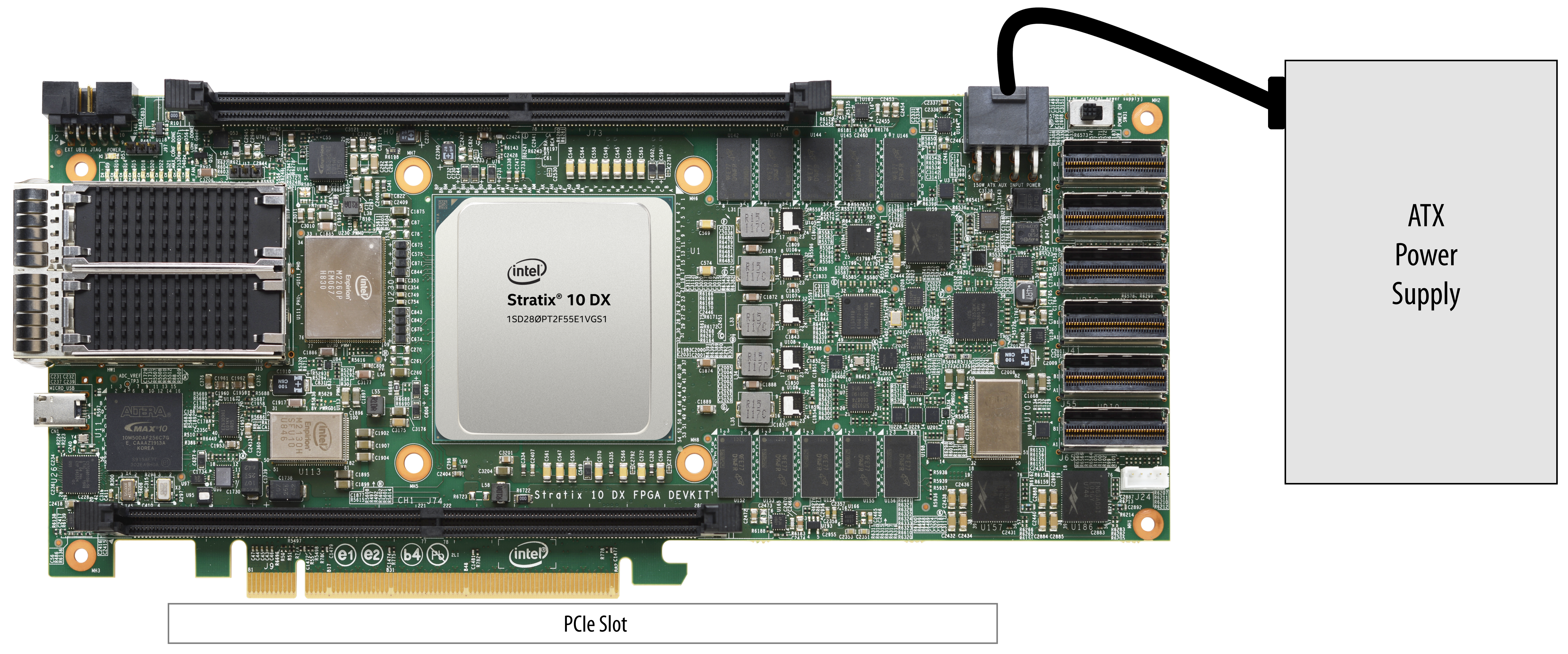
In this mode, plug the board into an available PCI Express slot and connect the standard 2x4 power cords available from the PC's ATX power supply to J11 on the board. The PCIe slot together with the auxiliary PCIe power cords are required to power the entire board. If you do not connect the 2x4 auxiliary power connection, the board does not power on. The power switch SW3 is ignored when the board is used in the PCIe system.Figure 32. Setup Example

- Standalone evaluation board powered by included power supply
In this mode, plug the included power supply into the 2x4 pin connector (J42) and the AC power cord of the power supply into a power outlet. This power supply provides the entire power to the board without the need to obtain power from the PCIe slot. The power switch SW31 controls powering of the board.Figure 33. Setup Example
