Visible to Intel only — GUID: djf1496958811893
Ixiasoft
Add Clock, Reset, and Avalon-MM components
Add Pre-Built Systems and Memory Test Microcore Components
Export Signals, Set Base Address Assignments, and Connect Memory Tester Interface Components
Resolve Interface Requirements and Value Mismatches
Replace the memory_tester_subsystem Generic Component
Synchronize IP Results
Visible to Intel only — GUID: djf1496958811893
Ixiasoft
Connect cpu_subsystem Components
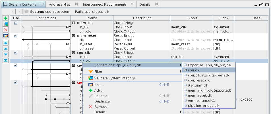
Connect the component signals below by clicking the dots across from the appropriate signals, or by right-clicking the signal and choosing from the drop-down menu.
Follow these steps to connect the components:
Figure 11. Illustrated Clock and Reset Component Connections for cpu_subsystem
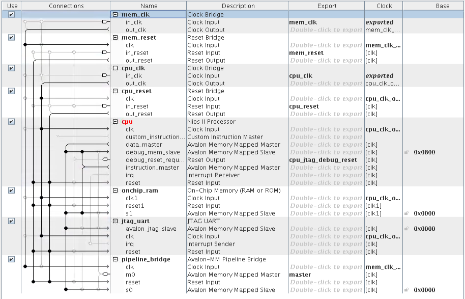
| Source Component/Signal | Target Component/Signal |
|---|---|
| mem_clk/out_clk | pipeline_bridge/clk |
| cpu_clk/out_clk |
|
| mem_reset/out_reset |
|
| cpu_reset/out_reset |
|
| cpu/data_master |
|
| cpu/instruction_master | onchip_ram/s1 |
Compare the finished connections to the following figure:
Figure 12. Component Connections for cpu_subsystem
System Connectivity Error appears in the System Messages tab. To access this tab, click View > System Messages. The System Connectivity Error occurs because when the base address of the Avalon-MM slaves are not assigned, which can cause address overlap.
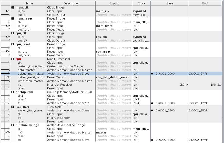
Follow these steps to assign the Base address to the value shown in the following figure. Click the “lock” icon to lock the address.
- In the Base column, click the value for Avalon Memory Mapped Slave (Description column) of the cpu component and type 12000.
- Find the Avalon Memory Mapped Slave entry for the onchip_ram component and type 10000 as the value in the Base column.
- Find the Avalon Memory Mapped Slave entry for the jtag_uart component and type 12800 as the value in the Base column.
Figure 13. Base Address Assignments for cpu_subsystem Components
- To resolve any remaining system connectivity errors, in the System Messages tab, click Sync All System Info in the bottom of the GUI. This synchronizes the component instantiations with their .ip files.
- To resolve errors in the parameterization of the cpu component (the name of the component is still red), double-click cpu and you can see the Parameterization Messages in the Parameters tab. Platform Designer separates the messages for system connectivity and component parameterization, which simplifies the error and resolution compared to the combined messaging in Platform Designer (Standard).
Figure 14. Parameterization Messages
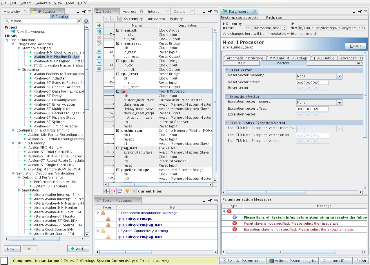
- In the Vectors tab, set Reset vector memory and Exception vector memory both to onchip_ram.s1 to resolve the error messages.
- Click File > Save to save the project. There is no need to generate the RTL for the Platform Designer system at this time. Click Move up one level of hierarchy to return to top_level.qsys system.
Figure 15. Move Up One Hierarchy Level