1.4.1. Test Case—Internal MAC Loopback
To run the hardware test case, follow these steps:
- Download the reference design from Design Store and restore the design using Intel® Quartus® Prime software.
- Launch the Intel® Quartus® Prime software and open the project file (top.qpf).
- Click to compile the design.
- After the design is compiled successfully, a programming file (top.sof) is generated and located in the <project_directory>/output_files directory.
Note: Warning (21608) appears in the compilation report because this design uses I/Os on the 3V I/O bank, which requires you to ensure that the VCCR_GXB and VCCT_GXB rails on the corresponding tile are powered up to avoid any configuration issues. Refer to the Intel® Stratix® 10 Device Family Pin Connection Guidelines for more details about the power rails. The Intel® Stratix® 10 GX L-Tile FPGA Development Board powers up the VCCR_GXB and VCCT_GXB rails by default, hence you can safely ignore this warning.
- Set up the Intel® Stratix® 10 GX L-Tile FPGA Development Board.
- Connect the programming cable to the JTAG connection port (CN1).
- Connect the power adapter to the power supply input (J27).
- In the Intel® Quartus® Prime software, select to launch the programmer.
- Download the generated programming file (top.sof) to the development board using the Programmer application.
- Reset the Ethernet design by either these methods:
- Press the USER_PB0 push button.
- Toggle the In-System Source and Probes bit[0] from 0 to 1 and back to 0 based on Figure 4.
- In the Intel® Quartus® Prime software, on the Tools menu, click In-System Sources and Probes Editor to open the In-System Sources and Probes Editor.
- In the JTAG Chain Configuration pane, point to Hardware, and then select Intel Stratix 10 GX L-Tile FPGA Development Board, as shown in the Programmer application.
- From the Device list, select Intel Stratix 10 Device, as shown in the Programmer application.
- Click the plus sign (+) on the side of source[0..0] to expand the bits list.
- Toggle the bit source[0] from 0 to 1 and back to 0.
Note: The design must be reset whenever you begin a new test. The reset must assert for at least 10 ms because the RESET_N pin of the Marvell PHY needs to be kept low for 10 ms, which is the minimum reset requirement of the Marvell PHY.
Figure 4. Reset Through In-System Sources and Probes Editor
- Open the config.tcl script using text editor, which is located in the <project_directory>/sc_tcl directory. Ensure that you set the following parameters accordingly to achieve intended operating speed rate and mode. For more information, refer to Configuration Script.
- Selection of speed rate:
- For 10 Mbps, set ETH_SPEED to 0 and to ENA_10 to 1.
- For 10/100/1000 Mbps, set ETH_SPEED to 0 and ENA_10 to 0.
- For 1000 Mbps only, set ETH_SPEED to 1 and ENA_10 to 0 or 1. However, Intel does not recommend this setting because it causes link failure if the PHY is running at 10/100 Mbps.
- Mode enablement for MAC loopback or PHY loopback:
- For MAC loopback, set LOOP_ENA to 1 and PHY_LOOPBACK to 1 or 0.
- For PHY loopback, set LOOP_ENA to 0 and PHY_LOOPBACK to 1.
- Selection of speed rate:
- In the Intel® Quartus® Prime software, select to launch the system console.
- In the System Console command shell, change the directory to <project_directory>/sc_tcl.
- Run the following command in the System Console command shell to start TSE MAC, TSE PCS, and on-board PHY chip configurations:
source config.tcl - Run the following command in System Console command shell to start generating and monitoring Ethernet packets:
source eth_gen_start.tclNote: Open the eth_gen_start.tcl script which located in <project_directory>/sc_tcl directory to set to desired configurations. For more information, refer to Configuration Script.The Ethernet Packet Monitor automatically starts after the Ethernet packet is generated. The System Console displays the number of packets with/without error received by the Ethernet Packet Monitor (refer to Figure 8).
- Run the following command to view the TSE MAC statistic counters:
source tse_stat_read.tcl
Figure 5. Sample Output—MAC Configuration Summary
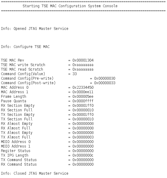
Figure 6. Sample Output—PCS Configuration Summary

Figure 7. Sample Output—On-Board PHY Chip Configuration Summary

Figure 8. Sample Output—Ethernet Packet Generator and Ethernet Packet Monitor Statistics
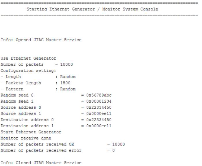
Figure 9. Sample Output—TX and RX MAC Statistic Counters
