Visible to Intel only — GUID: lly1513636244162
Ixiasoft
1. About the High Bandwidth Memory (HBM2) Interface Intel® FPGA IP
2. Introduction to High Bandwidth Memory
3. Stratix® 10 HBM2 Architecture
4. Creating and Parameterizing the High Bandwidth Memory (HBM2) Interface Intel® FPGA IP
5. Simulating the High Bandwidth Memory (HBM2) Interface Intel® FPGA IP
6. High Bandwidth Memory (HBM2) Interface Intel® FPGA IP Interface
7. High Bandwidth Memory (HBM2) Interface Intel® FPGA IP Controller Performance
8. High Bandwidth Memory (HBM2) Interface Intel® FPGA IP User Guide Archives
9. Document Revision History for High Bandwidth Memory (HBM2) Interface FPGA IP User Guide
4.2.1. General Parameters for High Bandwidth Memory (HBM2) Interface Intel® FPGA IP
4.2.2. FPGA I/O Parameters for High Bandwidth Memory (HBM2) Interface Intel® FPGA IP
4.2.3. Controller Parameters for High Bandwidth Memory (HBM2) Interface Intel® FPGA IP
4.2.4. Diagnostic Parameters for High Bandwidth Memory (HBM2) Interface Intel® FPGA IP
4.2.5. Example Designs Parameters for High Bandwidth Memory (HBM2) Interface Intel® FPGA IP
4.2.6. Register Map IP-XACT Support for HBM2 IP
5.1. High Bandwidth Memory (HBM2) Interface Intel® FPGA IP Example Design
5.2. Simulating High Bandwidth Memory (HBM2) Interface Intel® FPGA IP with ModelSim* and Questa*
5.3. Simulating High Bandwidth Memory (HBM2) Interface Intel® FPGA IP with Synopsys VCS*
5.4. Simulating High Bandwidth Memory (HBM2) Interface Intel® FPGA IP with Riviera-PRO*
5.5. Simulating High Bandwidth Memory (HBM2) Interface Intel® FPGA IP with Cadence Xcelium* Parallel Simulator
5.6. Simulating High Bandwidth Memory (HBM2) Interface Intel® FPGA IP for High Efficiency
5.7. Simulating High Bandwidth Memory (HBM2) Interface IP Instantiated in Your Project
6.1. High Bandwidth Memory (HBM2) Interface Intel® FPGA IP High Level Block Diagram
6.2. High Bandwidth Memory (HBM2) Interface Intel® FPGA IP Controller Interface Signals
6.3. User AXI Interface Timing
6.4. User APB Interface Timing
6.5. User-controlled Accesses to the HBM2 Controller
6.6. Soft AXI Switch
6.2.1. Clock Signals
6.2.2. Reset Signals
hbm_only_reset_in Timing
Reset Recommendations for Reliable Calibration of the HBM2 Interface
6.2.3. Calibration Status Signals
6.2.4. Memory Interface Signals
6.2.5. User-interface Signals
6.2.6. AXI User-interface Signals
6.2.7. Sideband APB Interface
6.2.8. Avalon® Memory-Mapped (AVMM) Interface Signals
7.1. High Bandwidth Memory (HBM2) DRAM Bandwidth
7.2. High Bandwidth Memory (HBM2) Interface Intel® FPGA IP HBM2 IP Efficiency
7.3. High Bandwidth Memory (HBM2) Interface Intel® FPGA IP Latency
7.4. High Bandwidth Memory (HBM2) Interface Intel® FPGA IP Timing
7.5. High Bandwidth Memory (HBM2) Interface Intel® FPGA IP DRAM Temperature Readout
Visible to Intel only — GUID: lly1513636244162
Ixiasoft
6.2.2. Reset Signals
| Signal | Direction | Description |
|---|---|---|
| wmcrst_n_in | Input | Core logic external input reset, active LOW. Resets all fabric logic, including the Soft Logic Adaptor. This is an asynchronous reset signal. You should assert this reset only when the AXI Interface is idle and there are no pending memory transactions. |
| hbm_only_reset_in | Input | Reset request for the soft fabric AXI logic as well as the hardened UIBSS, including the HBM2 DRAM, HBM Controller and PHY. From the Quartus® Prime software version 19.4 onwards, Intel® recommends to use only hbm_only_reset_in whenever you need to reset the HBM subsystem, both during active traffic to the DRAM or when the interface is idle. (See additional information immediately following this table.) |
| wmcrst_n_x_reset_n | Output | Core input reset synchronized to the AXI interface clock domain. One per AXI Channel (represented by x). Intel recommends that the user interface use the respective channel reset outputs in the logic that drives the AXI interfaces for the corresponding channels. |
hbm_only_reset_in Timing
The hbm_only_reset_in signal requests the reset of the soft AXI logic as well as the hardened UIBSS, and the HBM2 DRAM, without initiating a recalibration. This signal is supported only in the Quartus® Prime software version 19.4 and later.
The following waveform illustrates the timing associated with this signal.
Figure 17. hbm_only_reset_in Timing
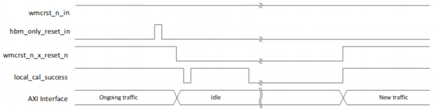
The following sequence explains the requirements and timing of the hbm_only_reset_in signal:
- The hbm_only_reset_in is a pulse driven asynchronous signal that is internally synchronized to the core clock (ext_core_clk). Therefore, to assert the hbm_only_reset_in, it should be driven from a low to high state and held in high state for at least one core clock cycle, and then transition the signal from high to low state. It is not possible to keep the HBM in reset indefinitely. Asserting hbm_only_reset_in high continuously does not result in any further resets, because a reset request is completed by a full low > high > low pulse.
- The wmcrst_n_in signal must be high before the hbm_only_reset_in signal is asserted.
- The wmcrst_n_x_reset_n signal is reset output synchronized to the core clock. Intel® recommends that you connect user logic reset to this reset output so that AXI traffic can be stopped during the reset sequence.
- The start of the reset sequence is indicated by wmcrst_n_x_reset_n going low.
- The end of the reset sequence is indicated by wmcrst_n_x_reset_n going high.
- The hbm_only_reset_in can be asserted again after wmcrst_n_x_reset_n goes high (reset completed). Any assertion of hbm_only_reset_in during the reset sequence is ignored.
- The local_cal_success signal deasserts for several core clock cycles after the reset sequence begins, however this does not perform a recalibration.
Reset Recommendations for Reliable Calibration of the HBM2 Interface
Observe the following reset signal guidelines for reliable calibration of the HBM2 interface:
-
Ensure that the Reset Release Intel® FPGA IP is instantiated in your design. This IP helps to hold the FPGA in reset until all registers and core logic are in user mode. Intel® recommends that you use the ninit_done output of the Reset Release Intel® FPGA IP as one of the initial inputs to your reset circuit. You can find this IP in the IP Catalog under Basic Functions > Configuration and Programming > Reset Release Intel FPGA IP. You can find more information on using this IP, in AN 891: Using the Reset Release Intel FPGA IP , available here: https://www.intel.com/content/www/us/en/programmable/documentation/prh1555609801770.html#iuj1556119879221.
Use the ninit_done signal output of this IP to gate the core input reset (wmcrst_n_in). The ninit_done output is active low; that is, ninit_done = 0 after FPGA enters user mode.
- Ensure that wmcrst_n_in (active low soft logic reset input) and hbm_only_reset_in (active high reset signal for soft logic as hard logic of the HBM subsystem) are not asserted until after completion of calibration.
- Commencing with the Quartus® Prime software version 19.4, Intel® recommends using hbm_only_reset_in whenever you need to reset the HBM subsystem, both during active traffic to the DRAM or when the interface is idle.
- The I/O PLL that generates ext_core_clk, the core AXI interface input clock, cannot be reset once the I/O PLL has achieved a locked condition.
- The wmcrst_n_x_reset_n signal that is driven as an output from the UIBSS per HBM2 channel (represented by x) is to be used by the user AXI interface along with the wmc_clk_x_clk provided per channel as shown in Figure 16.
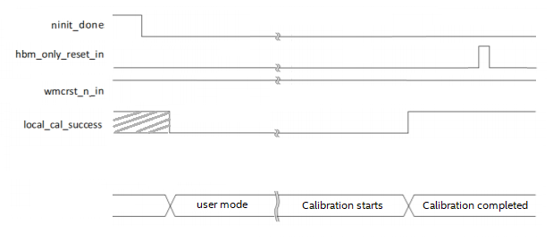
The following waveform illustrates the timing associated with these reset recommendations. Where, ninit_done initially transitions from high to low, indicating that the FPGA has entered user mode. Then, following this calibration should start, and while its ongoing wmcrst_n_in must be high and hbm_only_reset_in must be low.
Figure 18. Recommended Reset Timing
Related Information