Visible to Intel only — GUID: bzo1510104609529
Ixiasoft
1. About the High Bandwidth Memory (HBM2) Interface Intel® FPGA IP
2. Introduction to High Bandwidth Memory
3. Stratix® 10 HBM2 Architecture
4. Creating and Parameterizing the High Bandwidth Memory (HBM2) Interface Intel® FPGA IP
5. Simulating the High Bandwidth Memory (HBM2) Interface Intel® FPGA IP
6. High Bandwidth Memory (HBM2) Interface Intel® FPGA IP Interface
7. High Bandwidth Memory (HBM2) Interface Intel® FPGA IP Controller Performance
8. High Bandwidth Memory (HBM2) Interface Intel® FPGA IP User Guide Archives
9. Document Revision History for High Bandwidth Memory (HBM2) Interface FPGA IP User Guide
4.2.1. General Parameters for High Bandwidth Memory (HBM2) Interface Intel® FPGA IP
4.2.2. FPGA I/O Parameters for High Bandwidth Memory (HBM2) Interface Intel® FPGA IP
4.2.3. Controller Parameters for High Bandwidth Memory (HBM2) Interface Intel® FPGA IP
4.2.4. Diagnostic Parameters for High Bandwidth Memory (HBM2) Interface Intel® FPGA IP
4.2.5. Example Designs Parameters for High Bandwidth Memory (HBM2) Interface Intel® FPGA IP
4.2.6. Register Map IP-XACT Support for HBM2 IP
5.1. High Bandwidth Memory (HBM2) Interface Intel® FPGA IP Example Design
5.2. Simulating High Bandwidth Memory (HBM2) Interface Intel® FPGA IP with ModelSim* and Questa*
5.3. Simulating High Bandwidth Memory (HBM2) Interface Intel® FPGA IP with Synopsys VCS*
5.4. Simulating High Bandwidth Memory (HBM2) Interface Intel® FPGA IP with Riviera-PRO*
5.5. Simulating High Bandwidth Memory (HBM2) Interface Intel® FPGA IP with Cadence Xcelium* Parallel Simulator
5.6. Simulating High Bandwidth Memory (HBM2) Interface Intel® FPGA IP for High Efficiency
5.7. Simulating High Bandwidth Memory (HBM2) Interface IP Instantiated in Your Project
6.1. High Bandwidth Memory (HBM2) Interface Intel® FPGA IP High Level Block Diagram
6.2. High Bandwidth Memory (HBM2) Interface Intel® FPGA IP Controller Interface Signals
6.3. User AXI Interface Timing
6.4. User APB Interface Timing
6.5. User-controlled Accesses to the HBM2 Controller
6.6. Soft AXI Switch
7.1. High Bandwidth Memory (HBM2) DRAM Bandwidth
7.2. High Bandwidth Memory (HBM2) Interface Intel® FPGA IP HBM2 IP Efficiency
7.3. High Bandwidth Memory (HBM2) Interface Intel® FPGA IP Latency
7.4. High Bandwidth Memory (HBM2) Interface Intel® FPGA IP Timing
7.5. High Bandwidth Memory (HBM2) Interface Intel® FPGA IP DRAM Temperature Readout
Visible to Intel only — GUID: bzo1510104609529
Ixiasoft
3.2. Stratix® 10 UIB Architecture
The Stratix® 10 device architecture includes the universal interface bus (UIB) subsystem (UIBSS) which contains the necessary logic to interface the FPGA core to the HBM2 DRAM.
Each UIB subsystem includes the HBM2 hardened controller and the universal interface bus, consisting of the hardened physical interface and I/O logic needed to interface to each HBM2 DRAM device. The AMBA AXI4 protocol interfaces the core logic with the universal interface bus subsystem. An optional soft logic adapter implemented in the FPGA fabric helps to efficiently interface user logic to the hardened HBM2 controller. Commencing with the Quartus® Prime software version 20.2, an optional Avalon® memory-mapped interface is supported to each Pseudo Channel.
The following figure shows a high-level block diagram of the Stratix® 10 HBM2 universal interface bus subsystem. The UIB subsystem includes the following hardened logic:
- Rate-matching FIFOs that transfer logic from the user core clock to the HBM2 clock domain.
- HBM2 memory controller (HBMC).
- UIB PHY, including the UIB physical layer and I/O.
Figure 3. Block Diagram of Stratix® 10 HBM2 Implementation
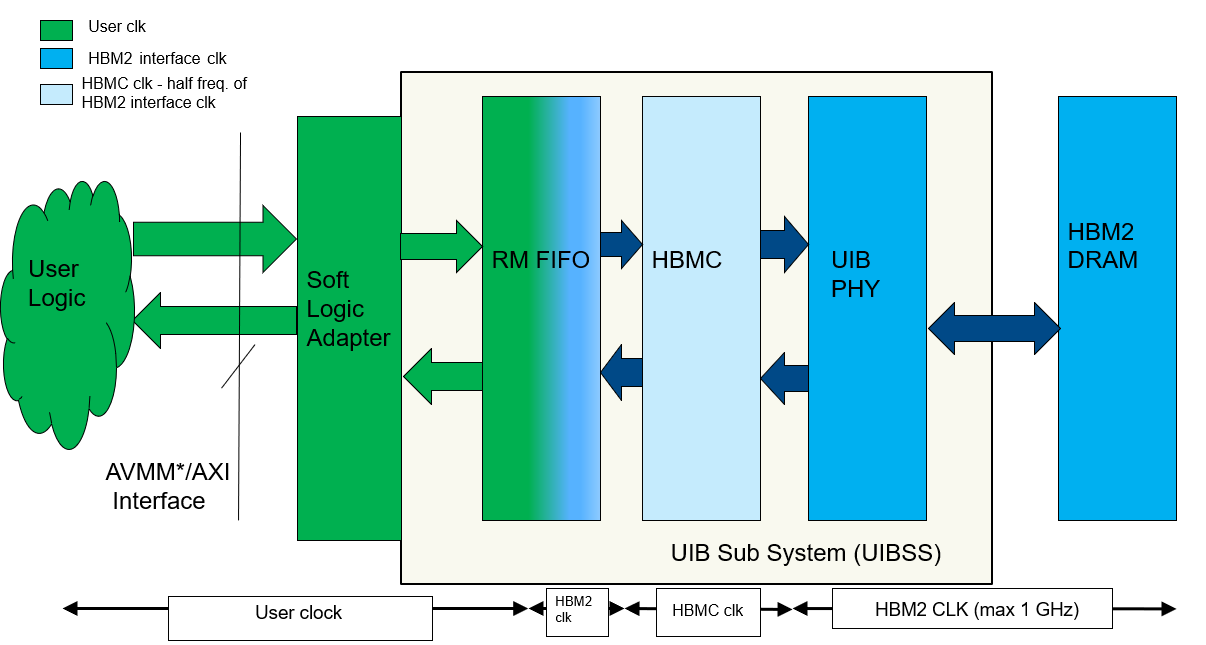
(* Avalon® memory-mapped interface is supported beginning with the Quartus® Prime software version 20.2.)
The user core clock drives the logic highlighted in green, while the UIB clocks the logic highlighted in blue. The UIB clock also drives the HBM2 interface clock. User logic can run up to one-to-four times slower than the HBM2 interface.
Soft Logic AXI Adaptor
The HBM2 IP also includes a soft logic adaptor implemented in FPGA core logic. The soft logic adaptor gates the user valid signals (write address valid, write data valid, and read address valid) with the corresponding pipelined ready signals from the HBM2 controller. The soft logic adapter also temporarily stores output from the HBM2 controller (AXI write response and AXI read data channels) when the AXI ready signal is absent. You can disable the temporary storage logic if user logic is always ready to accept output from the HBM2 controller through the parameter editor when generating the HBM2 IP.
HBM2 DRAM
The following table lists the HBM2 signals that interface to the UIB. The UIB drives the HBM2 signals and decodes the received data from the HBM2. These signals cannot be accessed through the AXI4 User Interface.
| Signal Name | Signal Width | Notes |
|---|---|---|
| Data | 128 | 128 bit bidirectional DQ per channel |
| Column command/address | 8 | 8-bit wide column address bits |
| Row command/address | 6 | 6-bit wide row address bits |
| DBI | 16 | 1 DBI per 8 DQs |
| DM_CB | 16 | 1 DM per 8 DQs. You can use these pins for DM or ECC, but not both. |
| PAR | 4 | 1 parity bit per 32 DQs |
| DERR | 4 | 1 data error bit per 32 DQs |
| Strobes | 16 | Separate strobes for read and write strobes. One differential pair per 32 DQs for read and write. |
| Clock | 2 | Clocks address and command signals |
| CKE | 1 | Clock enable |
| AERR | 1 | Address error |
The following table lists the HBM2 signals that are common to all Pseudo Channels in each HBM2 interface. The HBM2 controller interfaces with the following signals; these signals are not available at the AXI4 user interface.
| Signal Name | Signal Width | Notes |
|---|---|---|
| Reset | 1 | Reset input |
| TEMP | 3 | Temperature output from HBM2. |
| Cattrip | 1 | Catastrophic temperature sensor. |
The Stratix® 10 HBM2 IP supports only the Pseudo Channel mode of the HBM2 specification. Pseudo Channel mode includes the following features:
- Pseudo Channel mode divides a single HBM2 channel into two individual subchannels of 64 bit I/O.
- Both Pseudo Channels share the channel’s row and column command bus, CK, and CKE inputs, but decode and execute commands individually.
- Pseudo Channel mode requires a burst length of 4.
- Address BA4 directs commands to either Pseudo Channel 0 (BA4 = 0) or Pseudo Channel 1 (BA4 = 1). The HBM2 controller handles the addressing requirements of the Pseudo Channels.
- Power-down and self-refresh are common to both Pseudo Channels, due to a shared CKE pin. Both Pseudo Channels also share the channel’s mode registers.
User AXI Interface
Each Stratix® 10 HBM2 interface supports a maximum of eight HBM2 channels. Each HBM2 channel has two AXI4 interfaces, one per Pseudo Channel. Each AXI4 interface includes a 256-bit wide Write and Read Data interface per Pseudo Channel. The following figure shows the flow of data from user logic to the HBM2 DRAM through the UIBSS, while selecting HBM2 channels 0 and 7.
Figure 4. Stratix® 10 HBM2 Interface Using HBM2 Channels 0 and 7 through the UIBSS
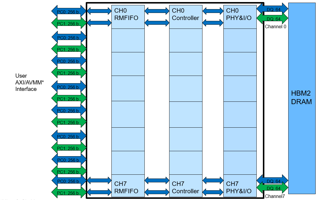
(* Avalon® memory-mapped interface is supported beginning with the Quartus® Prime software version 20.2.)
AXI User Interface
There is one AXI interface per Pseudo Channel. Each AXI interface supports a 256-bit wide Write Data interface and a 256-bit wide Read Data interface, to and from the HBM2 controller. The AXI4 protocol can handle concurrent writes and reads to the HBM2 controller. There is also a sideband user port per user channel pair, compliant to the Advanced Peripheral Bus (APB). The sideband provides access to user-controlled features such as refresh requests, ECC status, Power Down status, HBM2 temperature readout, Avalon® memory-mapped user interface, calibration status, and User Interrupt. AXI burst lengths are limited to 2 (arlen=1) when the HBM2 controller is configured in pseudo-BL8 mode. AXI burst lengths are limited to 1 (arlen=0) in HBM2 controller BL4 mode, unless the optional soft-logic burst length adapter is enabled in the controller channel configuration.
Avalon® Memory-Mapped Interface
Starting with the Quartus® Prime software version 20.2, a 256-bit Avalon® memory-mapped interface is supported per Pseudo Channel. The Avalon memory-mapped burst length must be exactly 1 when the HBM2 controller is configured in BL4 mode, and exactly 2 when the HBM2 controller is configured in pseudo-BL8 mode.
Soft AXI Switch
Beginning with the Quartus® Prime software version 20.1, the HBM2 IP supports a soft 4x4 AXI switch that provides each AXI master the ability to access the memory space of its corresponding two HBM2 Channels or four HBM2 Pseudo Channels (one HBM2 Channel = two HBM2 Pseudo Channels) in the HBM2 DRAM. The switch feature is not supported in the Avalon® memory-mapped interface flow. For more details on the AXI switch, refer to Soft AXI Switch.
For information on the AXI protocol features supported by the Stratix® 10 HBM2 controller, refer to High Bandwidth Memory (HBM2) Interface Intel® FPGA IP Interface.