3.2.2.2. Auto Neg Tab
The Auto Neg tab may have one or more subtabs based on number of times the device goes into Auto Negotiation (AN) state during the Signal Tap capture in a finite amount of time. Each subtab displays the Ethernet IP link behavior during the occurrence of AN. Each AN occurrence is also prefixed with a number to distinguish between various AN occurrences.
| Name | Signal 6 | Indication | Description |
|---|---|---|---|
| Auto Negotiation (AN) Enable | an_enable | LED |
|
| Auto Negotiation (AN) Done | an_done | LED |
|
| Local Auto Negotiation (AN) Technology | [lcl_tech] or [E25_TECH] | Text | Displays the Auto Negotiation technology broadcasted by the local device. |
| Final Auto Negotiation (AN) Technology | [hcd_40g, hcd_kr, hcd_xaui, hcd_gige] or [ieee_mode] or [e25_mode] | Text |
|
| Name | Signal | Indication | Description |
|---|---|---|---|
| Remote Device Auto Negotiation Technology | [lp_tech] or [lp_e25_mode] | Text |
|
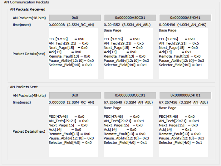
AN Communication Packet
The AN Communication Packet section displays the exchange of AN packets between two devices. There are two parts to the AN Communication Packets section:
- AN Packets Received—shows the sequence of AN packets (from left to right) received from a remote device.
- AN Packets Sent—shows sequence of AN packets (from left to right) sent to a remote device.
Figure 8. AN Communication Packet GUI
| Parameter | Description |
|---|---|
| AN Packets (48 bits) | Shows the Auto Negotiation packets exchanged between local and remote devices in hexadecimal format. |
| Time (msec) | Shows the SSM state in which AN packets are sent/received along with the timestamp with respect to reference timer |
| Packet Details (hex) | Shows the breakout for various bits in an AN packet and displays whether an AN packet in base page or next page.
Note: The assumption for BASE PAGE or NEXT PAGE only holds true when AN states are captured from the actual start point of Auto Negotiation (i.e., start point of SSM_RC_AN). If the AN states are captured partially in Signal Tap Logic Analyzer, this assumption becomes unreliable.
|
AN Arbiter State Machine
The AN Arbiter State Machine section displays the AN Arbiter State Machine in the form of time domain waveforms. The AN arbiter state machine represents the entire Ethernet IP link behavior in the AN mode of operation.
Each waveform window represents a timescale for one Sequencer State Machine (SSM) state (i.e., SSM_RC_AN, SSM_AN_ABL or SSM_AN_CHK). The time scale of waveform windows, such as START and STOP time, should match the timestamp of the corresponding SSM state. The waveform windows are also tagged with specific SSM states, as shown in the following figure:
Figure 9. Time Domain Waveforms of the Sequencer State Machine States
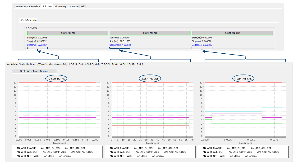
Each AN Arbiter SM state is represented as an individual waveform. A logic 1 value on a state waveform at a particular timestamp signifies the current state of the device at that timestamp. Device can possibly be in only one state at a given point of time. To change the magnification level of the waveforms, click the left mouse button and drag the mouse cursor to the bottom right of the waveform windows to zoom in and drag the mouse cursor the top right of the waveform windows to zoom out.
Note: While zooming in and out, the waveform windows may be offset in the vertical scale. This may cause several waveform windows in a row to be misaligned for logic 0 and 1. To remove any misalignments and scale the Y axis of all waveform window to a common scale, click on the Scale Waveforms (Y-axis) button.
Figure 10. Flowchart of AN Arbiter State MachineThis figure shows a flow chart of the AN Arbiter State Machine and the conditions that drives the next state, based on the current state.
| Name | Indication | Description |
|---|---|---|
| AN_ARB_ENABLE | Waveform | This is the initial state of the AN Arbiter State Machine. This should be enabled (logic 1 value) during SSM_RC_AN state. This state ends after the start of SSM_AN_ABL and the local device moves to the next state i.e., AN_ARB_TX_DIS. |
| AN_ARB_TX_DIS | Waveform | In this state, the TX output of the local device is disabled for a finite amount of time to allow the remote device to start Auto Negotiation. This causes to link to go down. The duration of this state can be 60 to 75 ms. Device should always complete this state irrespective if there is a remote device available or not. |
| AN_ARB_ABL_DET | Waveform | In this state, the local device send out the AN Base Page and waits for the AN base page from the remote device. The local device goes into this state at the end of SSM_AN_ABL. The local device waits in this state until the AN Base page is received and the corresponding Acknowledgement (ACK) is sent out to the remote device. The local device moves to next state after sending ACK to the remote device. If the ACK is not received from the remote device at this time, the local device moves to AN_ARB_ACK_DET where it waits for ACK from the remote signal. Else, the local device moves to AN_ARB_COMP_ACK, which indicates the completion of ACK exchange between the two devices. |
| AN_ARB_ACK_DET | Waveform | In this state, the local device is waiting for ACK from the remote device. |
| AN_ARB_COMP_ACK | Waveform | When an acknowledgement is sent to as well as received from the remote device, the local device moves to this state called the Ack Complete state. |
| AN_ARB_AN_GOOD | Waveform | This state indicates that AN has successfully completed on local device and is the final state of AN Arbiter State Machine. |
| AN_ARB_NXT_PAGE | Waveform | This state shows that the local device is sending NEXT page and waits for NEXT page from the remote device. This state remains until the local device send ACK to the remote device. |
| Name | Indication | Description |
|---|---|---|
| an_enable | Waveform | Displays when AN is enable. This is waveform representation of the AN Enable signal described in Table 6. |
| an_done | Waveform | Displays when AN is completed successfully. This is waveform representation of the AN Done signal described in Table 6. |
6 Actual signal names in the IP design file.