AD9371 EVM Software Setup
The AD9371 Transceiver evaluation software is used to generate the setup files for the AD9371 device and AD9528 clock generator for JESD204B link operation. For more information about AD9371 Transceiver evaluation software, visit the Analog website.
Setup files for each of the parameter configurations are included in the software installation in the form of predefined profiles. You need to generate the C scripts using the profiles with correct settings for the JESD204B link to operate at the targeted data rate and JESD204B link parameters.
Follow these steps to generate the configuration C scripts via the AD9371 Transceiver evaluation software graphical user interface (GUI):
- Start the AD9371 Transceiver Evaluation Software (TES). Figure 3 shows the opening page of TES.
Figure 3. AD9371 TES interface
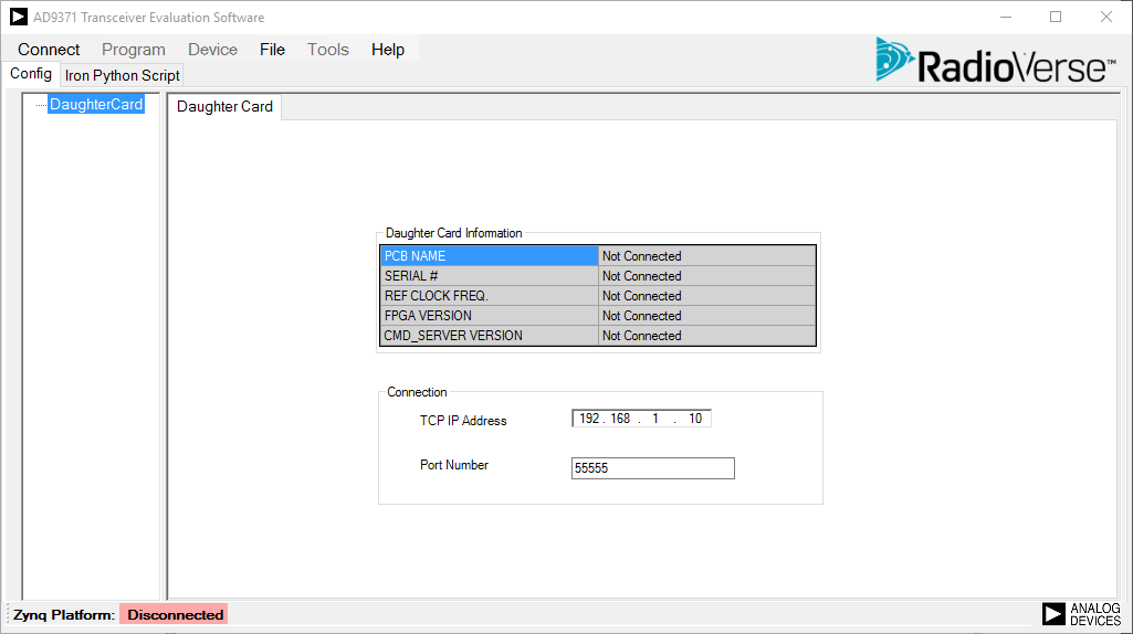
- In the case when evaluation hardware is not connected, the user can still use the software in demonstration mode by following these steps:
- Click Connect (top left corner).
- The Zynq board is disconnected message appears; click OK. After clicking OK, the software enters demonstration mode in which a subset of all features is displayed as shown in Figure 4.
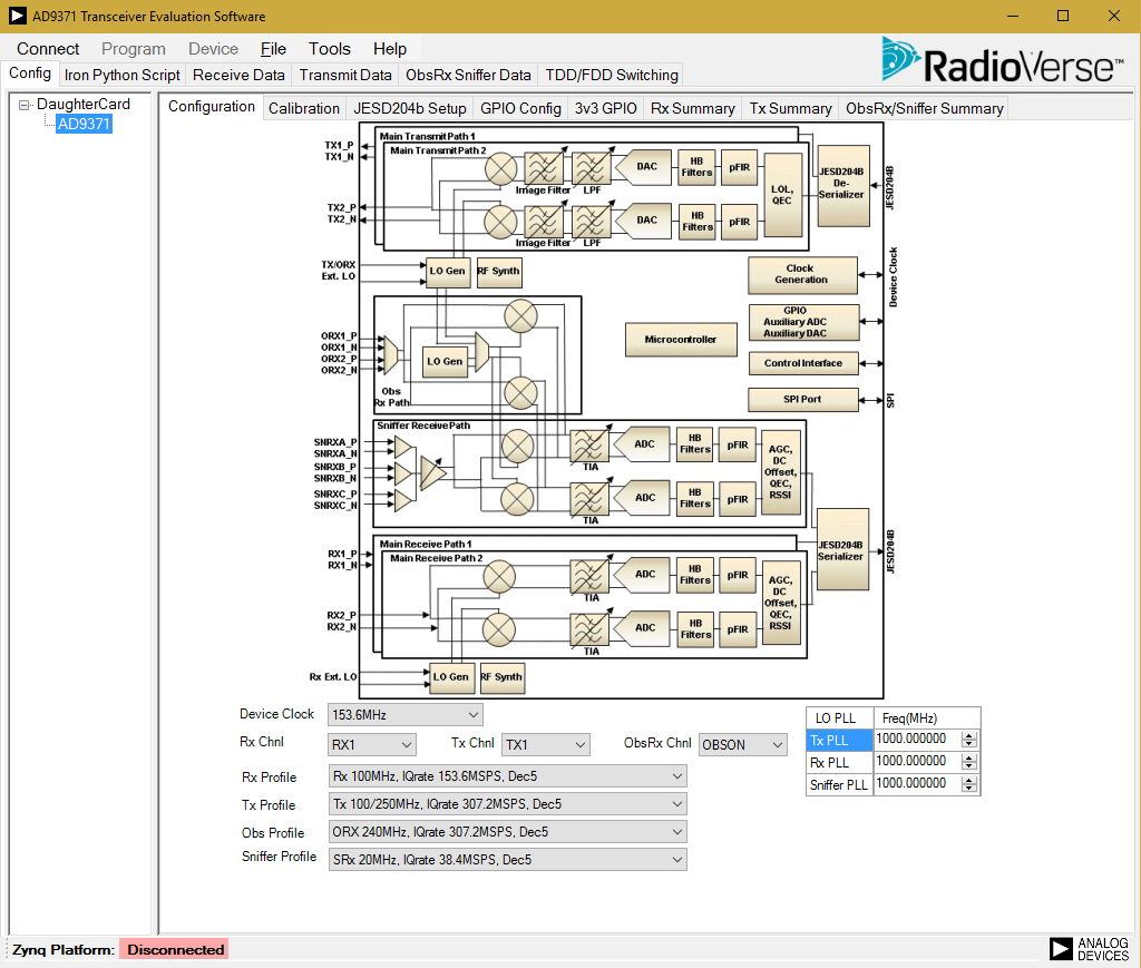
- The first tab displayed is the Configuration tab. Selecting this tab opens the initial screen, as shown in Figure 4. The following selections are available from this tab:
- Device clock frequency
- Number of active Rx channels
- Number of active Tx channels
- Select observation/Sniffer input
- Select profiles for Rx, Tx, ORx, and Sniffer Rx
- Select Rx, Tx, and SnRx/ORx RF frequency
- The AD9371 provides a observation receiver (ORx ADC). The SERDES for main receiver datapath and observation receiver datapath are shared, but they have independent JESD204B framers (For more information, refer to the AD9371 User Guide). In this interoperability report, only the main ADC datapath has been considered.
Figure 4. TES configuration tab
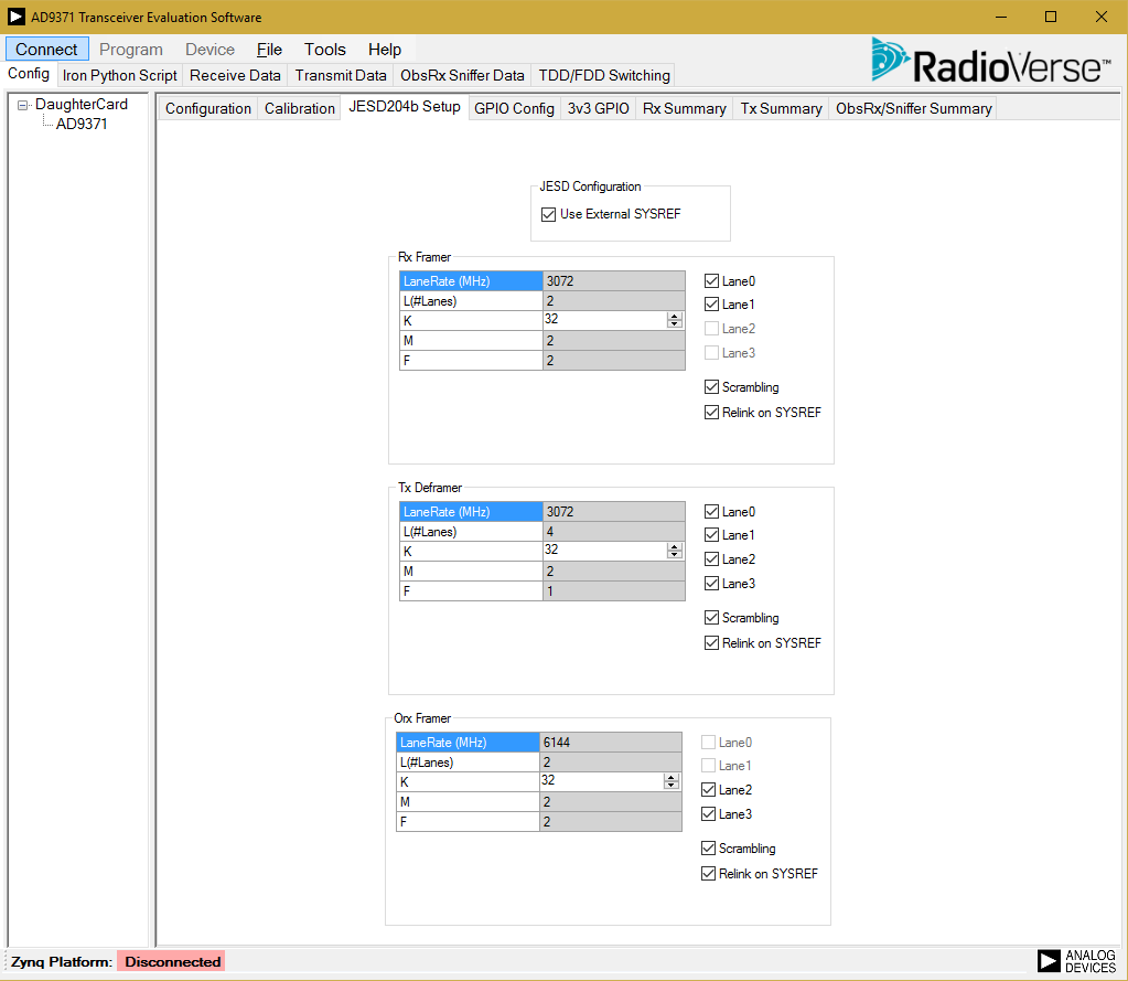
- Set the Configurations based on the requirements and move to JESD204b setup tab, which appears as shown in Figure 5.
- In this tab, set the required JESD link parameters and lane rate for both Tx Deframer (DAC) and Rx Framer (Main ADC).
Figure 5. JESD204B setup tab
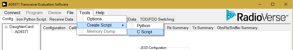
- After configuring the GUI with required settings, the C scripts for configuring the EVM can be generated by clicking on Tools -> Create Script -> C script as shown in Figure 6. Save the file with name “myk_config” so that the existing software makefiles can be used for compiling the scripts.
Figure 6. Generating configuration C scripts