Visible to Intel only — GUID: ifu1512323519339
Ixiasoft
1.1. Acronyms and Definitions
1.2. Recommended System Requirements
1.3. Installation Folders
1.4. Boot Flow Overview
1.5. Getting Started
1.6. Enabling the UEFI DXE Phase and the UEFI Shell
1.7. Using the Network Feature Under the UEFI Shell
1.8. Creating your First UEFI Application
1.9. Using Arm* DS-5* Intel® SoC FPGA Edition (For Windows* Only)
1.10. Pit Stop Utility Guide
1.11. Porting HWLIBs to UEFI Guidelines
1.12. Tera Term Installation
1.13. Minicom Installation
1.14. Win32DiskImager Tool Installation
1.15. TFTPd64 By Ph.Jounin Installation
1.16. Revision History of Intel® Arria® 10 SoC UEFI Boot Loader User Guide
1.5.1. Compiling the Hardware Design
1.5.2. Generating the Boot Loader and Device Tree for UEFI Boot Loader
1.5.3. Building the UEFI Boot Loader
1.5.4. Creating an SD Card Image
1.5.5. Creating a QSPI Image
1.5.6. Booting the Board with SD/MMC
1.5.7. Booting the Board with QSPI
1.5.8. Early I/O Release
1.5.9. Booting Linux* Using the UEFI Boot Loader
1.5.10. Debugging an Example Project
1.5.11. UEFI Boot Loader Customization
1.5.12. Enabling Checksum for the FPGA Image
1.5.13. NAND Bad Block Management
Visible to Intel only — GUID: ifu1512323519339
Ixiasoft
1.5.10.1. Configuring and Starting the Debugger in Eclipse
This task describes how to configure your project setting to use Eclipse with the Arm* DS-5* Intel® SoC FPGA Edition debugger.
- Connect the mini USB cable from the Intel® Arria® 10 SoC FPGA development board Intel® FPGA Download Cable II port to the PC.
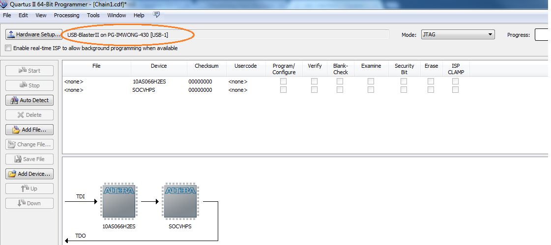
- Verify that your JTAG Intel® FPGA Download Cable II can detect the devices. The diagram below shows an example.
Figure 85. Verifying Device Detection
- Start the Eclipse application if it is not yet started. Select Start Menu > All Programs > ARM DS-5 > Eclipse for DS-5 to start Eclipse from the program search window. Alternatively, you can start Eclipse from the Embedded Command Shell window.
- The Eclipse tool, part of the Arm* DS-5* Intel® SoC FPGA Edition, prompts for the workspace folder to be used. You can use the suggested folder and click OK.
- The Arm* DS-5* Intel® SoC FPGA Edition Welcome screen appears. You can use this screen to access documentation, tutorials and videos.
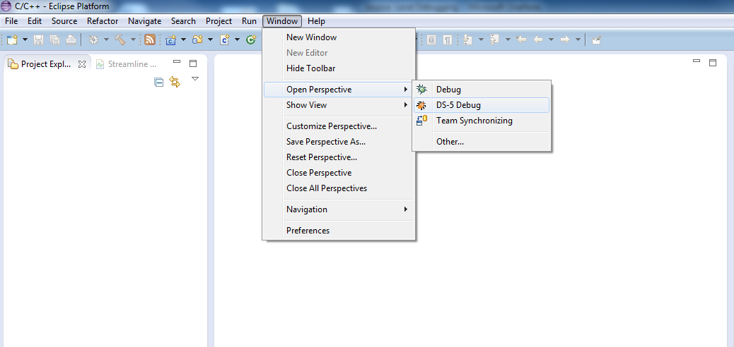
- Select Window > Open Perspective > DS-5 Debug to open the workbench.
Figure 86. Opening the DS-5 Workbench
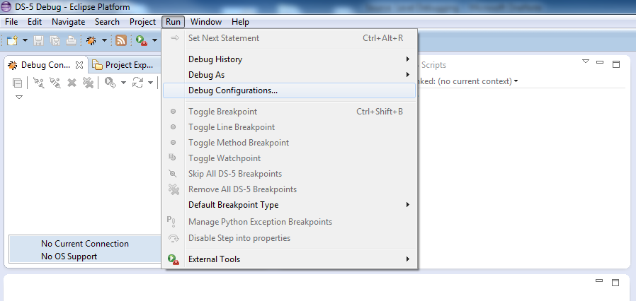
- Select Run > Debug Configurations... to access the launch configurations.
Figure 87. Opening Debug Configurations
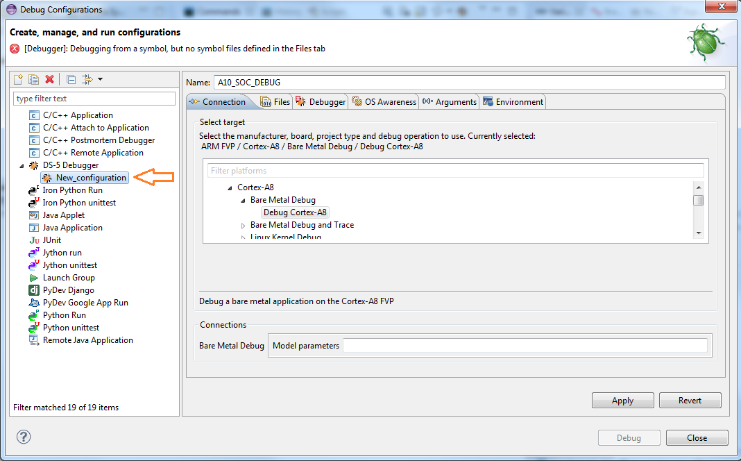
- In the Debug Configuration dialog box left panel, select DS-5 Debugger > New_configuration
Figure 88. Opening New Configuration
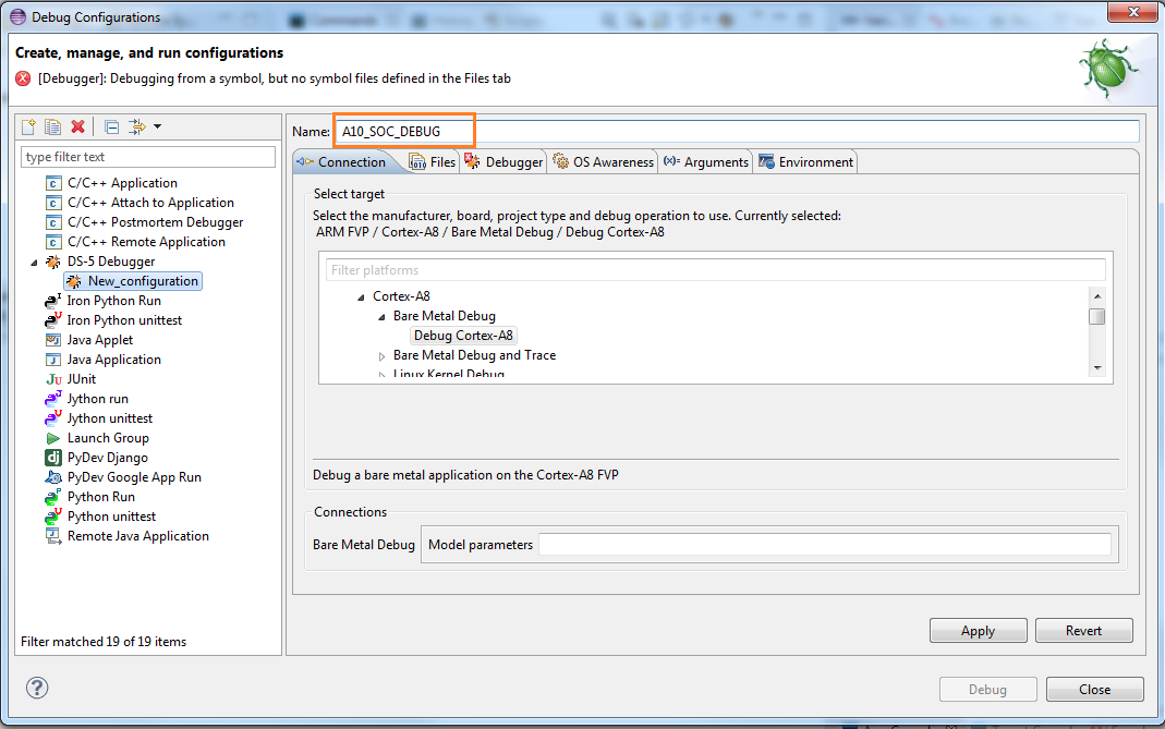
- Enter your preferred Name. In the example shown below, the Name text field has an entry of A10_SOC_DEBUG.
Figure 89. New Configuration Name Text Field
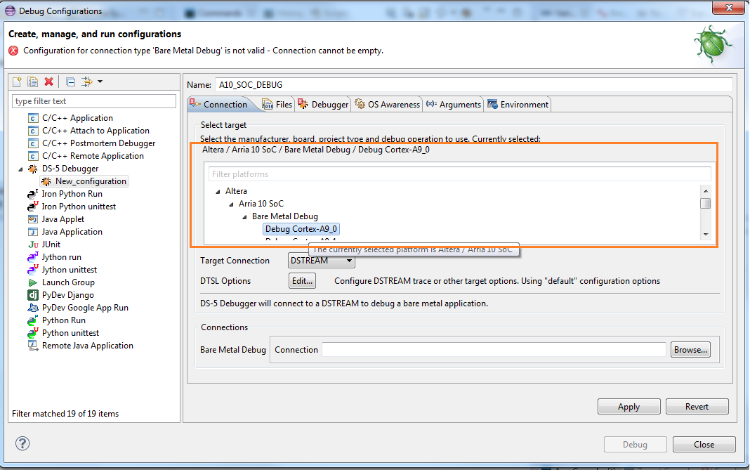
- Configure the target to be Altera > Arria 10 SoC > Bare Metal Debug > Debug Cortex-A9_0.
Figure 90. Configure Target Connection
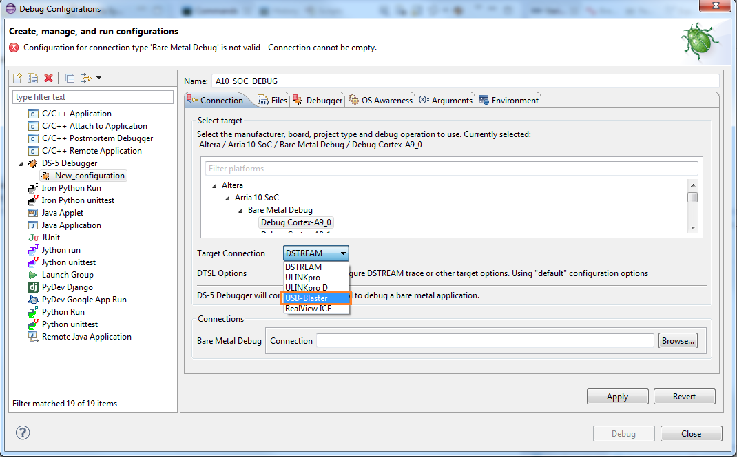
- In the Target Connection pull-down menu, select USB-Blaster connection.
Figure 91. Select USB Blaster Connection
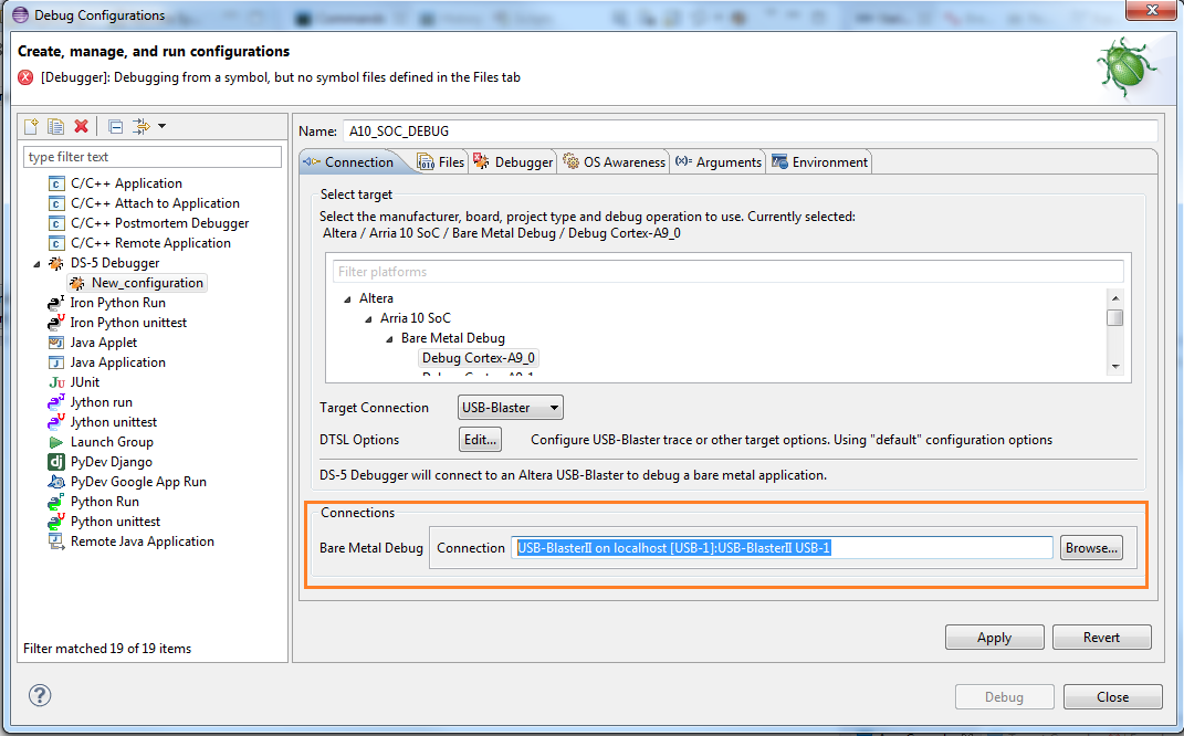
- For the Bare Metal Debug Connection, click Browse… and select USB-BlasterII on localhost [USB-1]:USB-BlasterII USB-1.
Figure 92. Selecting Bare Metal Debug Connection
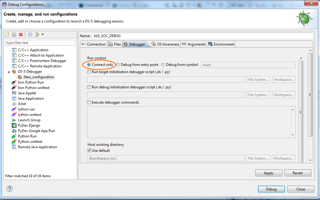
- Select the Debugger tab and select the Connect only option.
Figure 93. Connect Only Selection for Run Control
- Click the Debug button.
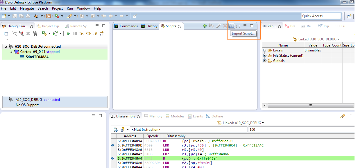
- In the DS-5 Debug window, select Import Script….
Figure 94. Import Script
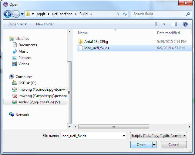
- Browse to your Arm* DS-5* Intel® SoC FPGA Edition script location under Build/load_uefi_fw.ds. In this example, /data/<username>/pggit/uefi-socfpga/Build/load_uefi_fw.ds is selected.
Figure 95. Browsing to the load_uefi_fw.ds File
- Click Open.
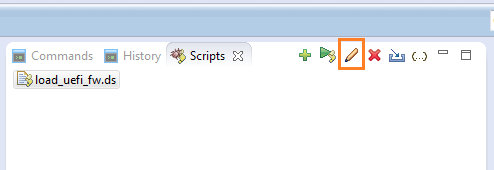
- Edit your load_uefi_fw.ds file by selecting the pencil icon.
Figure 96. Editing the load_uefi_fw.ds File
- Verify the load_uefi_fw.ds file loads the correct Build/PEI.256 path. If not, edit the path to locate the correct Build/PEI.256 file path. In this example, the PEI.256 file is found at: /data/<username>/pggit/uefisocfpga/Build/PEI.256. Make the following change from the screenshot below:
Figure 97. Original PEI.256 PathTo the following path:
 Figure 98. Modified PEI.256 Path
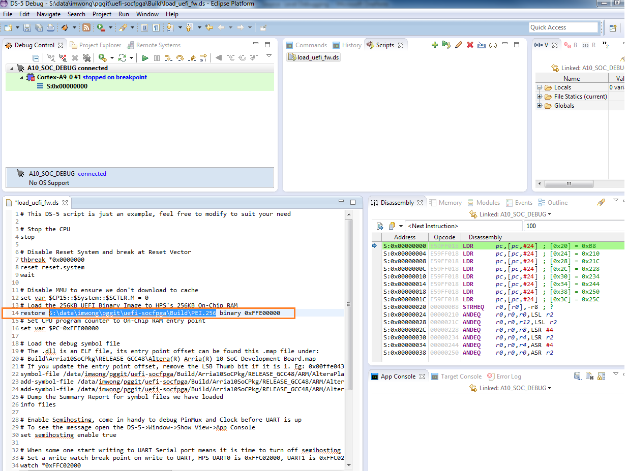
- Click Save.
- Double-click the load_uefi_fw.ds file to run the updated script.
- If you encounter the error messages below, verify that you have edited the load_uefi_fw.ds to the correct path. Proceed to step 24 if you do not see this error.
Figure 99. Error Message Window
- Click Save and double-click the load_uefi_fw.ds file to run the updated script.
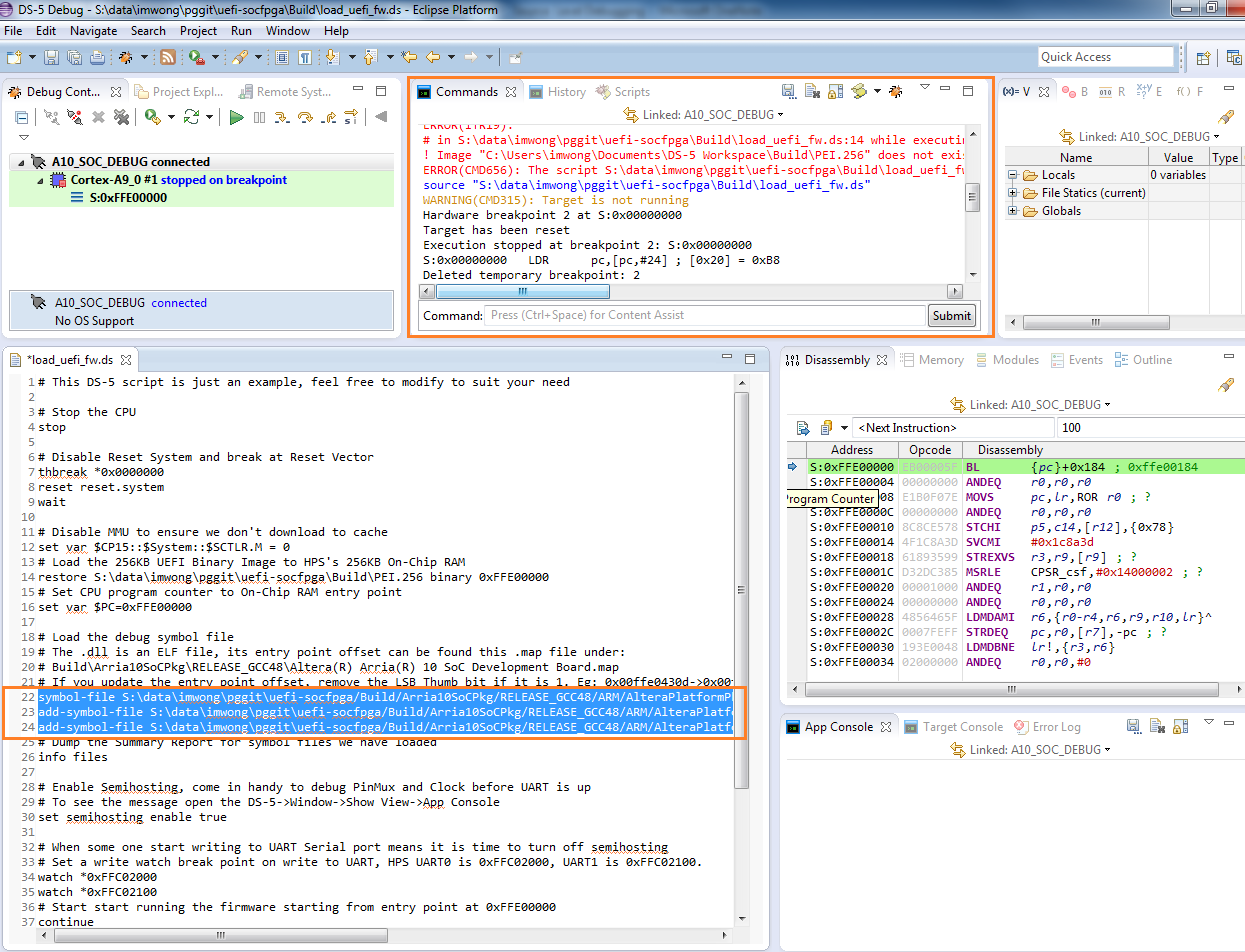
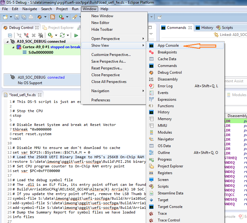
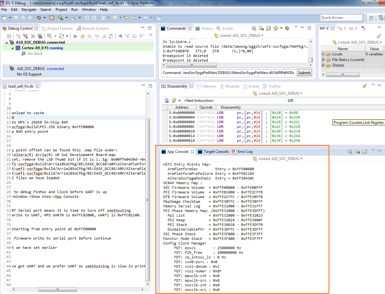
- Select Window > Show View > App Console to enable the App Console window.
Figure 100. Enabling the App Console Window
- Click the continue green arrow to run the application.
- The following content appears in the App Console window:
Figure 101. App Console Window
At the same time, pin multiplexing configuration output messages appear on the serial terminal program window.
Figure 102. Serial Terminal Pin Multiplexing Configuration Output Messages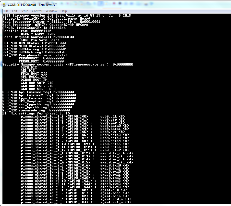
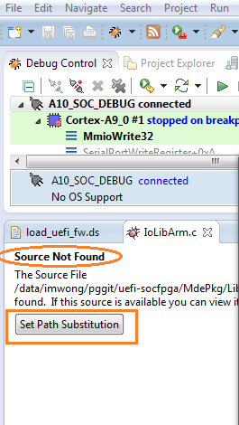
- Use the Outline view to edit and view your source file. If you encounter a "Source Not Found" error, click Set Path Substitution.
Figure 103. Correcting a "Source Not Found" Error
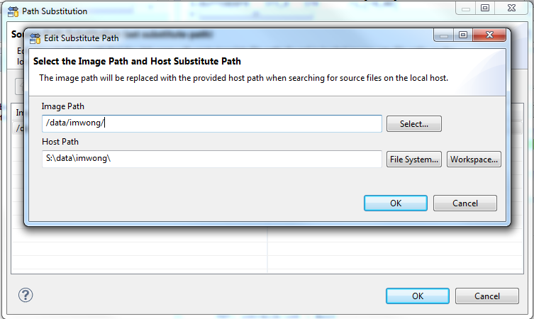
- When the Edit Substitute Path dialog box appears, configure the Host Path to the correct path and click OK.
Figure 104. Configuring the Host Path